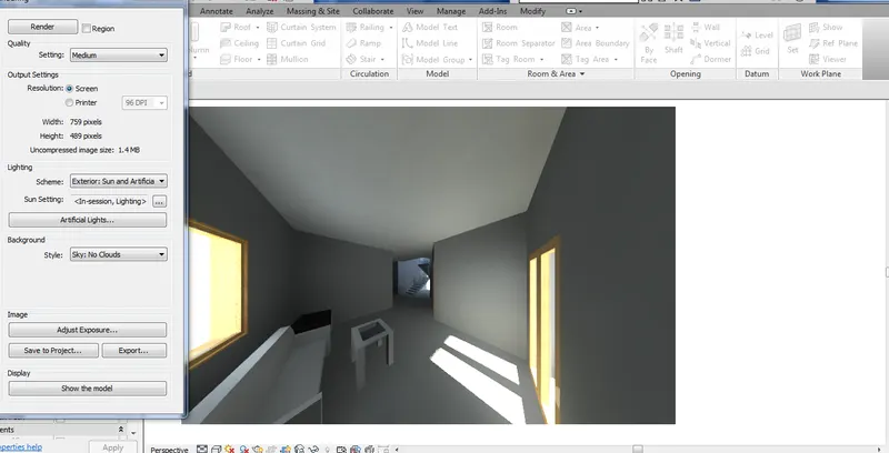
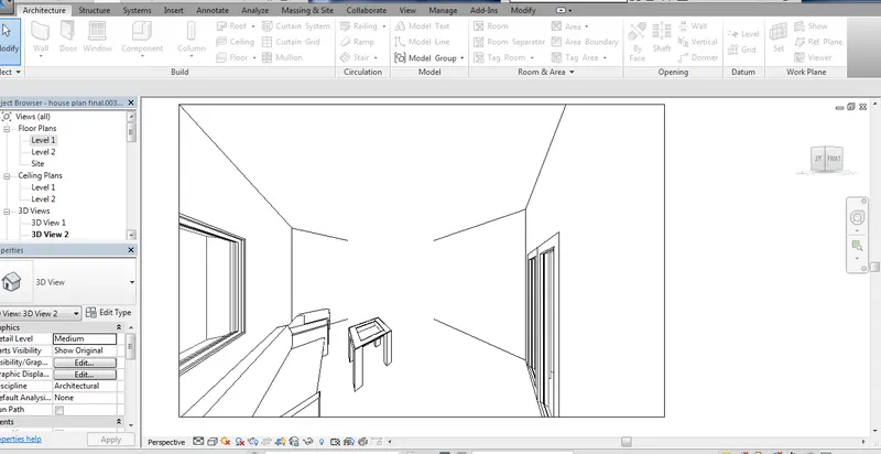
3D Creation of Celing, Roof, Architectural plan, Structural plan, Sectional view, Elevation view and Camera specific view for a house plan using REVIT
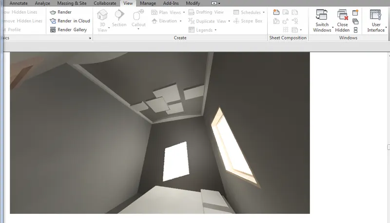
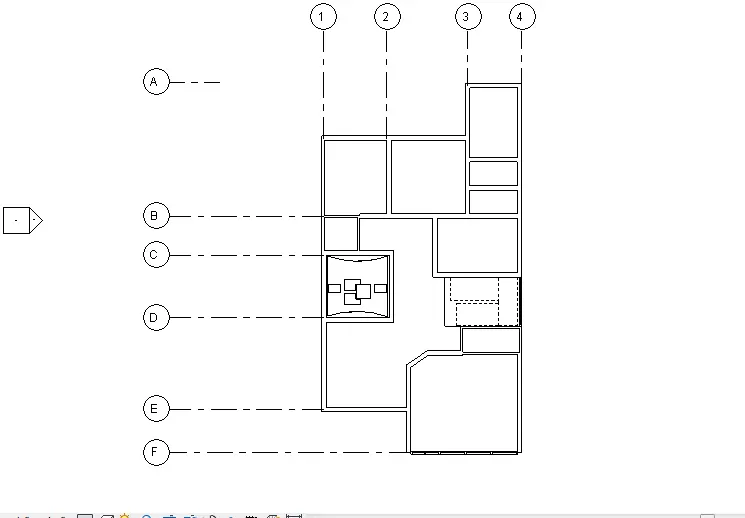
AIM : Based on the project saved from Week 3, proceed from the First Floor Level. Model a Ceiling from the architecture tab above the walls at the first-floor level
Introduction : An overhead interior surface that covers the upper limits of a room .
It is not generally considered a structural element, but a finished surface concealing the underside of the roof structure or the floor of a story above.
Ceilings can be decorated to taste, and there are many fine examples of frescores and artwork on ceilings especially in religious buildings..
A ceiling can also be the upper limit of a Tunnel
The most common type of ceiling is the dropped Ceiling which is suspended from structural elements above.
Panels of drywall are fastened either directly to the ceiling joists or to a few layers of moisture-proof plywood which are then attached to the joists. Pipework or ducts can be run in the gap above the ceiling, and insulation and fireproofing material can be placed here. Alternatively, ceilings may be spray painted instead, leaving the pipework and ducts exposed but painted, and using spray form .
Procedure :
Step 1: As per the plan Design in week 3 plan open the plan
Step 2: Go to Architecture option in tool bar and open Ceiling option
Step 3: Then in modify tool bar select rectangle option and drag the rectangle from the one side corner of room to another side corner of room
Step 4: Click on Correct Button or click on offcet option and specify the offcet as 18" and select pick line
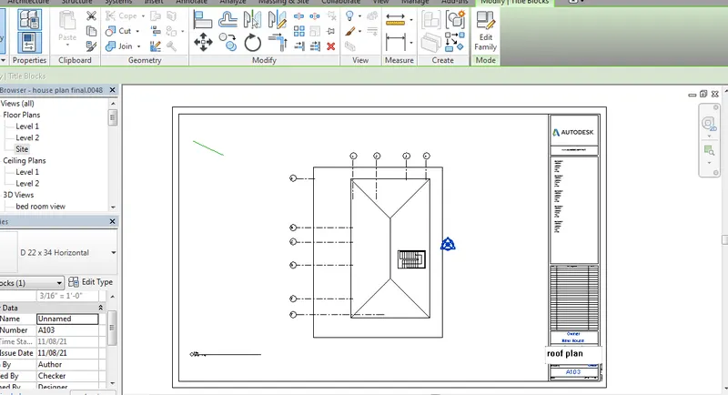
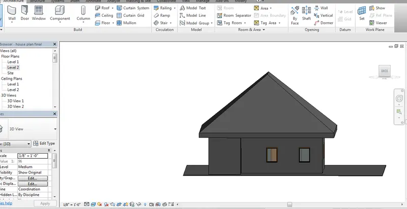
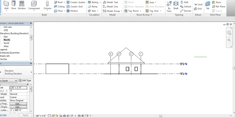
AIM : Model a roof above the ceiling by selecting the footprints of the ceiling. Using the adjustment toolbars appearing on-screen adjust the roof slope to 10 degrees
Introduction : An overhead interior surface that covers the upper limits of a room .
It is not generally considered a structural element, but a finished surface concealing the underside of the roof structure or the floor of a story above.
Ceilings can be decorated to taste, and there are many fine examples of frescores and artwork on ceilings especially in religious buildings..
A ceiling can also be the upper limit of a Tunnel
The most common type of ceiling is the dropped Ceiling which is suspended from structural elements above.
Panels of drywall are fastened either directly to the ceiling joists or to a few layers of moisture-proof plywood which are then attached to the joists. Pipework or ducts can be run in the gap above the ceiling, and insulation and fireproofing material can be placed here. Alternatively, ceilings may be spray painted instead, leaving the pipework and ducts exposed but painted, and using spray form .
Procedure :
Step 1: As per the plan Design in week 3 plan open the plan
Step 2: Go to Architecture option in tool bar and open the roof option and select the roof by foot print as it get the option slope of the roof
Step 3: Then in modify tool bar select rectangle option and drag the rectangle from the one side corner of room to another side corner of room
Step 4: Click on Correct Button or click on offcet option and specify the slope as 10" and select pick line
AIM : Using annotate toolbar add dimensions to all the walls and floors with reference to the longitudinal and transverse grids created in the project file
Introduction : An overhead interior surface that covers the upper limits of a room .
It is not generally considered a structural element, but a finished surface concealing the underside of the roof structure or the floor of a story above.
Ceilings can be decorated to taste, and there are many fine examples of frescores and artwork on ceilings especially in religious buildings..
A ceiling can also be the upper limit of a Tunnel
The most common type of ceiling is the dropped Ceiling which is suspended from structural elements above.
Panels of drywall are fastened either directly to the ceiling joists or to a few layers of moisture-proof plywood which are then attached to the joists. Pipework or ducts can be run in the gap above the ceiling, and insulation and fireproofing material can be placed here. Alternatively, ceilings may be spray painted instead, leaving the pipework and ducts exposed but painted, and using spray form .
Procedure :
Step 1: As per the plan Design in week 3 plan open the plan
Step 2: Go to Architecture option in tool bar and open the roof option and select the roof by foot print as it get the option slope of the roof
Step 3: Then in modify tool bar select rectangle option and drag the rectangle from the one side corner of room to another side corner of room
Step 4: Click on Correct Button or click on offcet option and specify the slope as 10" and select pick line
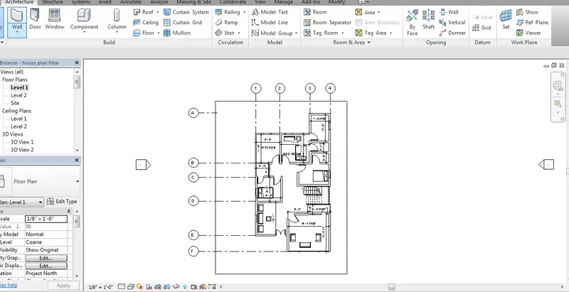
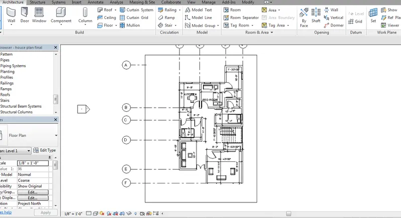
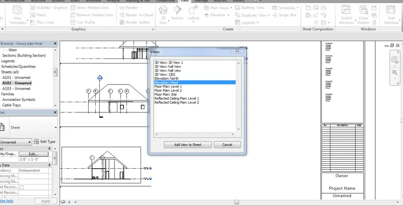
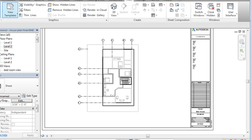
Aim: Create a sheet template from the view tab and adjust the parameters on the sheet to add appropriate views
Introduction : An overhead interior surface that covers the upper limits of a room .
It is not generally considered a structural element, but a finished surface concealing the underside of the roof structure or the floor of a story above.
Ceilings can be decorated to taste, and there are many fine examples of frescores and artwork on ceilings especially in religious buildings..
A ceiling can also be the upper limit of a Tunnel
The most common type of ceiling is the dropped Ceiling which is suspended from structural elements above.
Panels of drywall are fastened either directly to the ceiling joists or to a few layers of moisture-proof plywood which are then attached to the joists. Pipework or ducts can be run in the gap above the ceiling, and insulation and fireproofing material can be placed here. Alternatively, ceilings may be spray painted instead, leaving the pipework and ducts exposed but painted, and using spray form .
Procedure :
Step 1: As per the plan Design in week 3 plan open the plan
Step 2: Go to the view option and select the sheet composition
Step 3: Select the place sheet option
Step 4: Open it in the sheet view
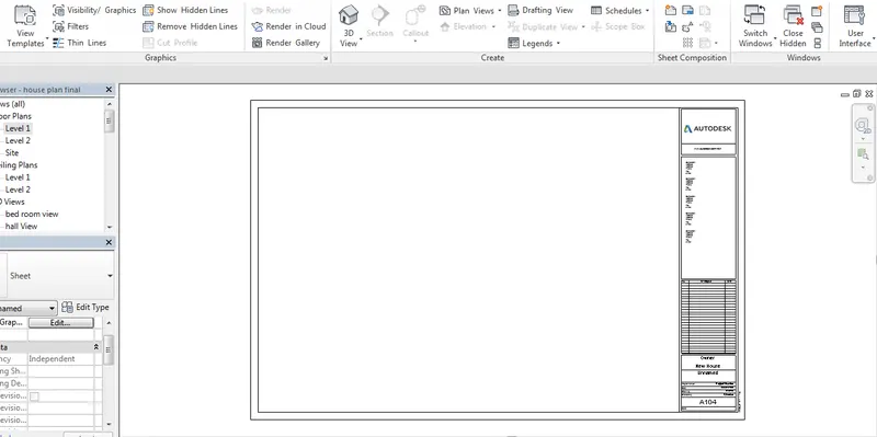
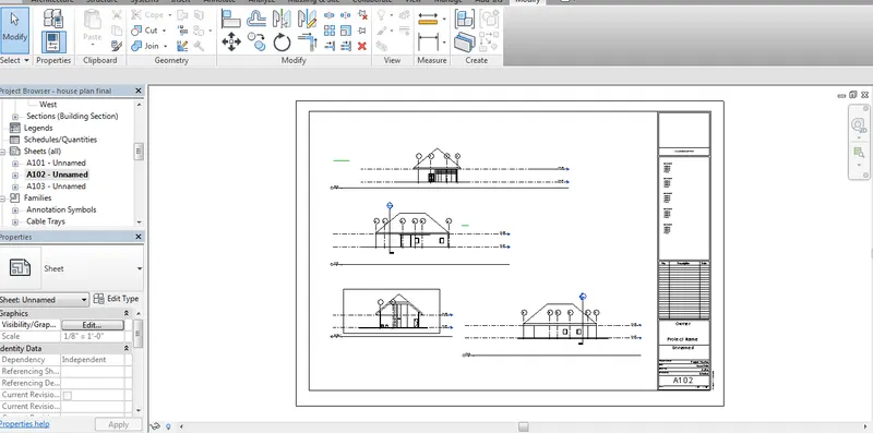
AIM : Using the elevation tab create the elevation views, looking at your building from East, North, South, and West
Introduction : An overhead interior surface that covers the upper limits of a room .
It is not generally considered a structural element, but a finished surface concealing the underside of the roof structure or the floor of a story above.
Ceilings can be decorated to taste, and there are many fine examples of frescores and artwork on ceilings especially in religious buildings..
A ceiling can also be the upper limit of a Tunnel
The most common type of ceiling is the dropped Ceiling which is suspended from structural elements above.
Panels of drywall are fastened either directly to the ceiling joists or to a few layers of moisture-proof plywood which are then attached to the joists. Pipework or ducts can be run in the gap above the ceiling, and insulation and fireproofing material can be placed here. Alternatively, ceilings may be spray painted instead, leaving the pipework and ducts exposed but painted, and using spray form .
Procedure :
Step 1: As per the plan Design in week 3 plan open the plan
Step 2: Go to Project Browser and open the Elevation view select the East , West, North , South Elevation
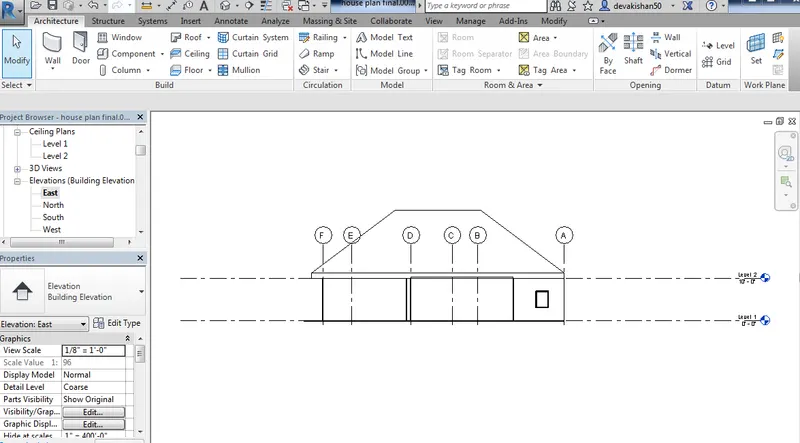
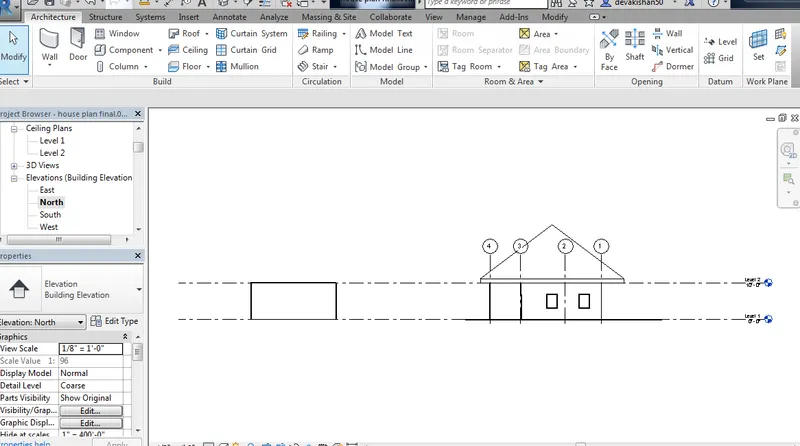
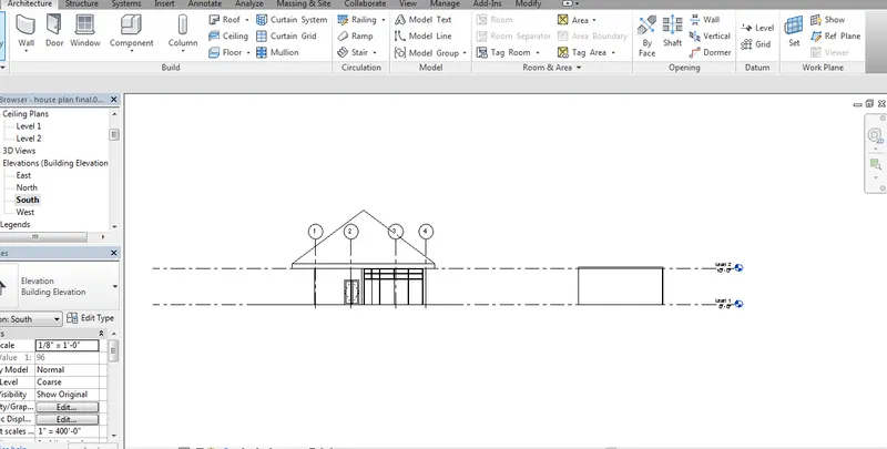
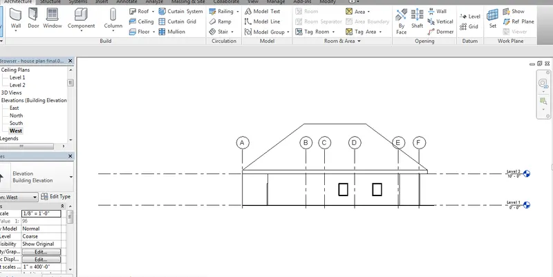
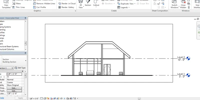
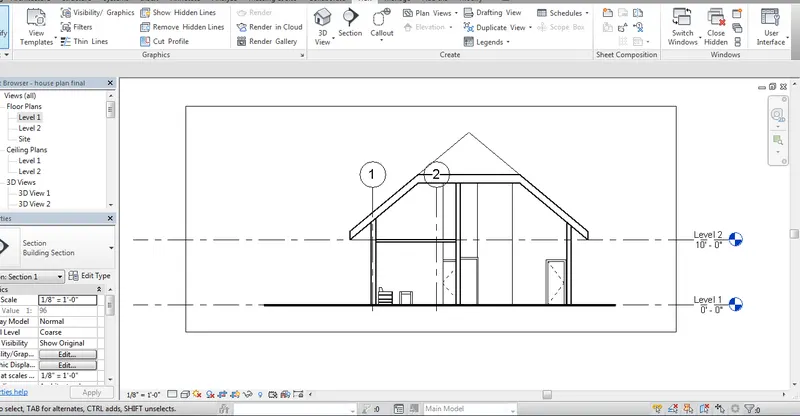
AIM : Produce section cut through each room either cutting across longitudinally or in a transverse direction
Introduction : An overhead interior surface that covers the upper limits of a room .
It is not generally considered a structural element, but a finished surface concealing the underside of the roof structure or the floor of a story above.
Ceilings can be decorated to taste, and there are many fine examples of frescores and artwork on ceilings especially in religious buildings..
A ceiling can also be the upper limit of a Tunnel
The most common type of ceiling is the dropped Ceiling which is suspended from structural elements above.
Panels of drywall are fastened either directly to the ceiling joists or to a few layers of moisture-proof plywood which are then attached to the joists. Pipework or ducts can be run in the gap above the ceiling, and insulation and fireproofing material can be placed here. Alternatively, ceilings may be spray painted instead, leaving the pipework and ducts exposed but painted, and using spray form .
Procedure :
Step 1: As per the plan Design in week 3 plan open the plan
Step 2: Go to Architecture option in tool bar and open view
Step 3: Then by view in section
Step 4: Select the view in the that you want to cut the section in view
AIM : Classify the views, Plan Views, Section Views, and Elevation views to either Design or Documentation category using Properties browser
Introduction :
- Plan views: floor plans, reflected ceiling plans, structural plans
- Elevation views
- Section views.
- 3D views
Procedure :
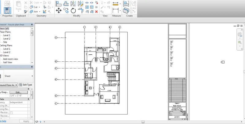
Plan View
In Plan view the view fromthe top of the can bee seen that contain the information of the Building in the form of the 2d line that may seperate the rooms of the building
In plan view the placement of the doors , windows are located in plan
The size of the room , location of the room and the dimension of the room are placed in the plan view
In plan view the location of the grids which represent the easy identification of the item in the plan
Section view
In section is the view which we can see the view of the particular building that was cut at the middle
in section view we can see the Height of the building thickness of the wall height of the Doors, windows
Elevation view
In Elevation view the view that can bee seen from the front side or the particular view of the building
In Elvation view we can see the height of the building from all sides
Type of elevation Elevation East, west , North , south
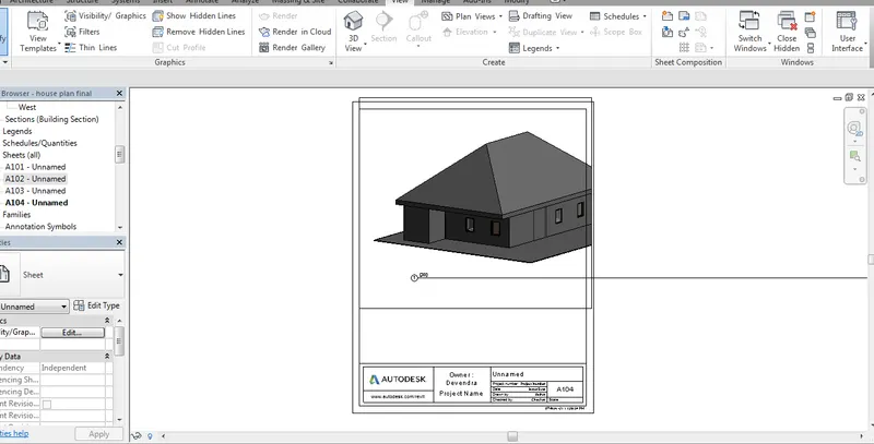
AIM : Using the sheet template produced create multiple sheets as follows
a. A 101- Ground Floor Architecture Plan
b. A 102- First Floor Architecture Plan
c. A 103- Roof Plan
d. S 101- Ground Floor Structural Plan
e. S 102- First Floor Structural Plan
f. S 103- Roof Framing Plan
g. A-201- North-South Elevations
h. A-202- East-West Elevations
INTRODUCTION :
Sheets are the template in Revit used to place the view of drawings in a single Document
All the Information about the drawing and the project are present in the sheet like the project name , location of project , drawing name , Drawing number etc
All the information required for the project are mention in the drawing so that it is very easy to understand the engineer to exicute the work at the site.
PROCEDURE:
Step 1: As per the plan Design in week 3 plan open the plan
Step 2: Open the main tool bar view option and open the Sheet composition
Step 3: In sheet composition select the place sheet option
Step 4: Click on insert family option and select the toolabar and selcet the sheet as per the documentation required