3D Creation of Celing, Roof, Architectural plan, Structural plan, Sectional view, Elevation view and Camera specific view for a house plan using REVIT
1. AIM: To model a Ceiling from the architecture tab above the walls at the first-floor level.
INTRODUCTION:
- The creation of Ceilings within Revit is a very similar process to that of Floors and Roofs
- Revit will let you place Ceilings in Floor Plan Views.
PROCEDURE:
Step 1:
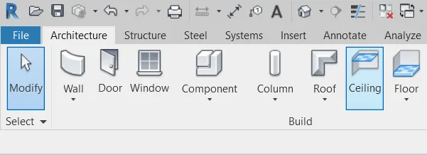
Step 2:
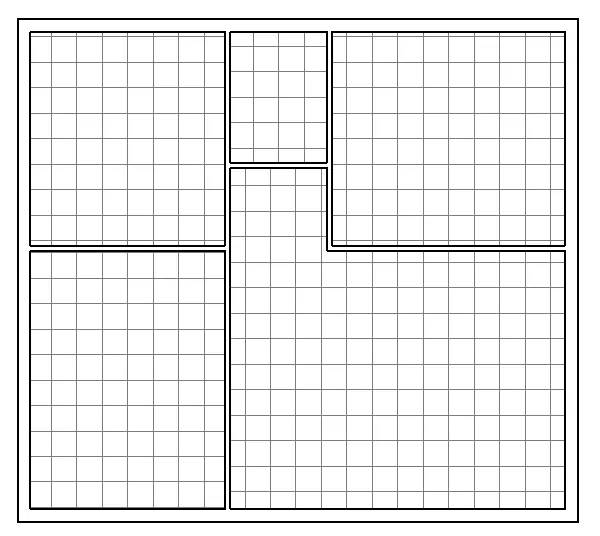
Step 3:
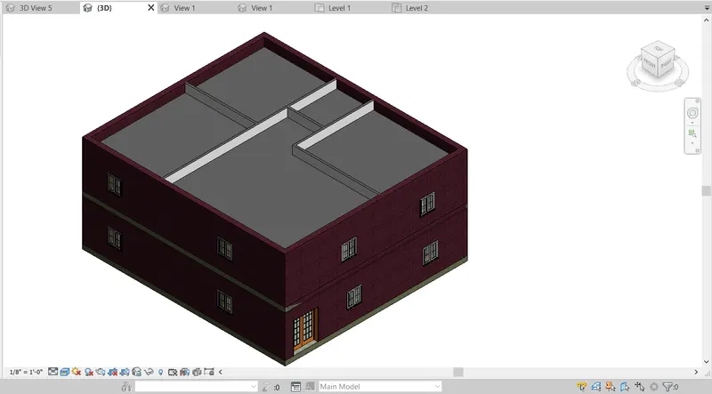
RESULT: The ceiling has been modelled successfully
2. AIM: To model a roof above the ceiling by selecting the footprints of the ceiling.
INTRODUCTION:
- Roof, covering of the top of a building, serving to protect against rain, snow, sunlignt wind, and extremes of temperature.
- Roofs have been constructed in a wide variety of forms flat, pitched, vaulted, domed
PROCEDURE:
Step 1:
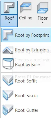
Step 2:
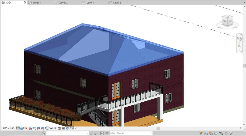
Step 3:
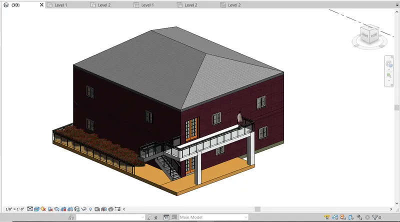
RESULT: The roof has been created successfully to the model
3. AIM: To create plan views for ground floor level and first-floor level including all the walls, floors, and components and to Separate them to architecture and structural plans.
INTRODUCTION:
- The structural plan view is the default view when you start a new project using a structural template.
- Most projects include at least one structural plan. New structural plan views are created automatically as you add new levels to your project. You can create multiple structural plan view types.
- The floor plan view is the default view in a new architectural project.
- Most projects include at least one floor plan.
- Floor plan views are created automatically as you add new levels to your project.
PROCEDURE:
Step 1:
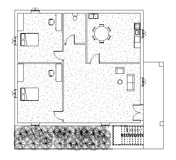
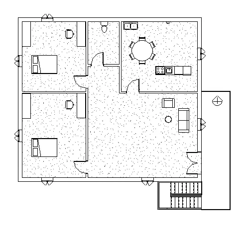
Step 2:
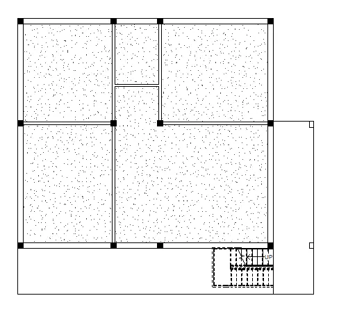
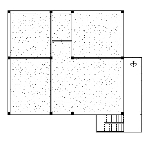
RESULT:-
- Created plan views for ground floor level and first-floor level including all the walls, floors, as well as components and separated them into architecture and structural plans.
4. AIM: To add dimensions to all the walls and floors with reference to the longitudinal and transverse grids created in the project file.
INTRODUCTION:
- The structural plan view is the default view when you start a new project using a structural template.
- Most projects include at least one structural plan. New structural plan views are created automatically as you add new levels to your project. You can create multiple structural plan view types.
- The floor plan view is the default view in a new architectural project. Most projects include at least one floor plan.
- Floor plan views are created automatically as you add new levels to your project.
PROCEDURE:
Step 1:
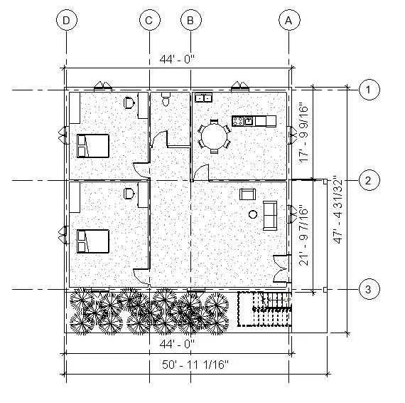
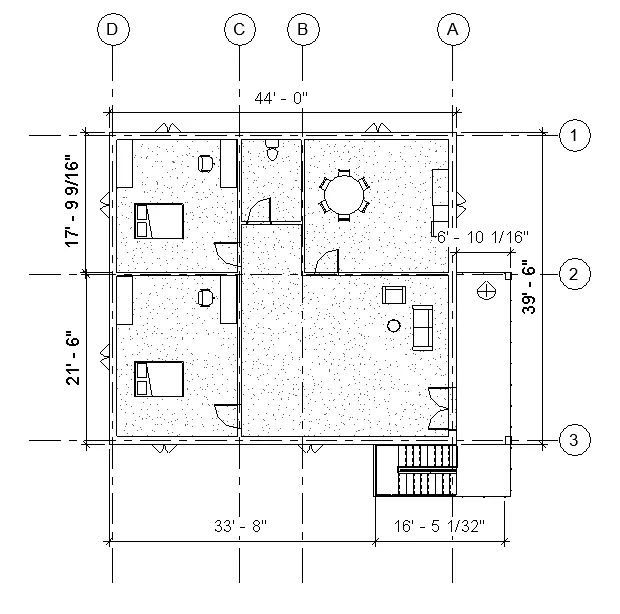
Step 2:
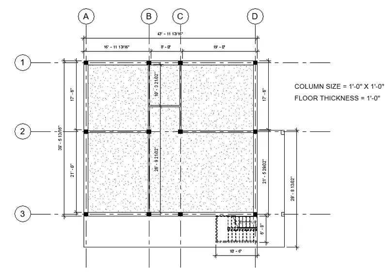
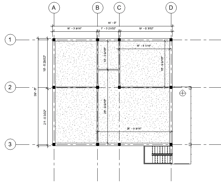
RESULT:
- The dimensions are added to the structural floor plans and architectural floor plans
- Longitudinal and transverse grids are created in the project file.
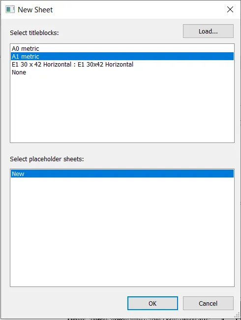
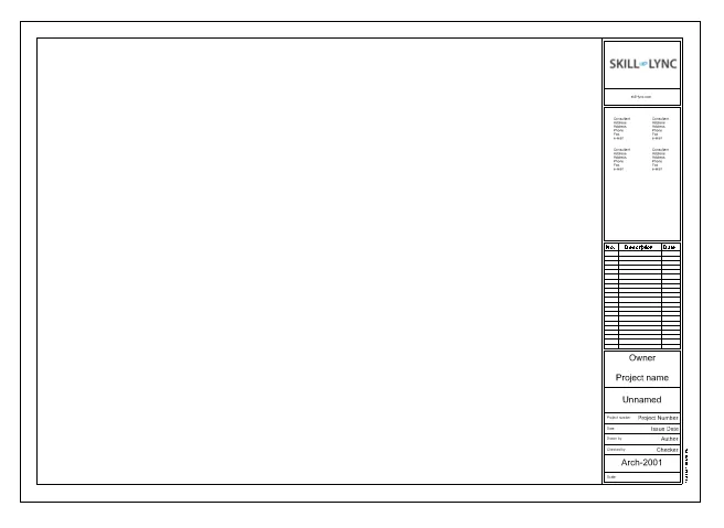
5. AIM: To create a sheet template from the view tab and adjust the parameters on the sheet to add appropriate views.
INTRODUCTION:
- Create views on a project template before you start building the model
- When creating a project template, you can include sheets in the template
PROCEDURE:
Step 1:
Step 2:
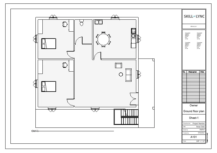
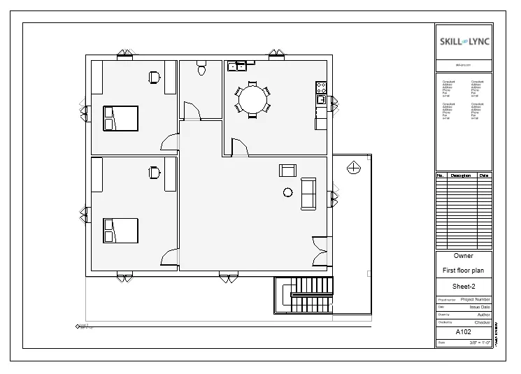
RESULT: Sheet template is created from view tab and parameters are adjusted on the sheet for adding appropriate views.
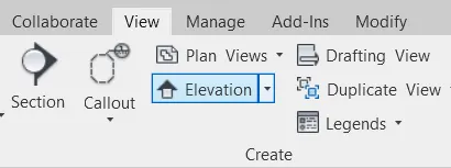
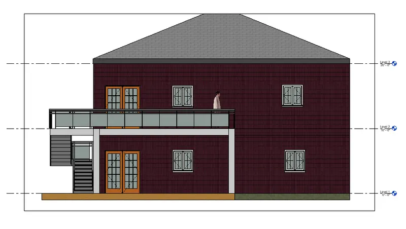
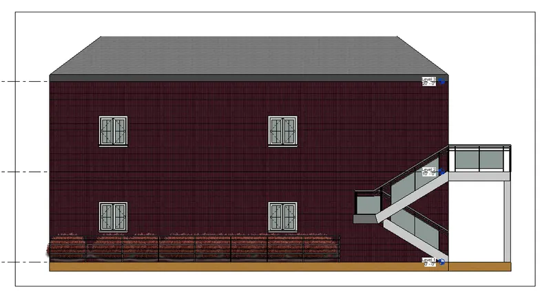
6. AIM: To create the elevation views, looking at your building from East, North, South, and West using the elevation tab.
INTRODUCTION: An elevation is a view of a building seen from one side, a flat representation of one view.
PROCEDURE:
Step 1:
Step 2:
- East elevation
Step 3:
- South elevation
Step 4:
- North elevation
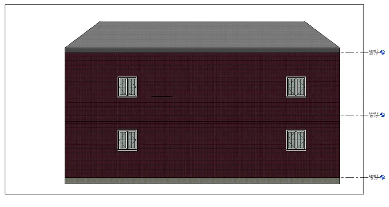
Step 5:
- West elevation
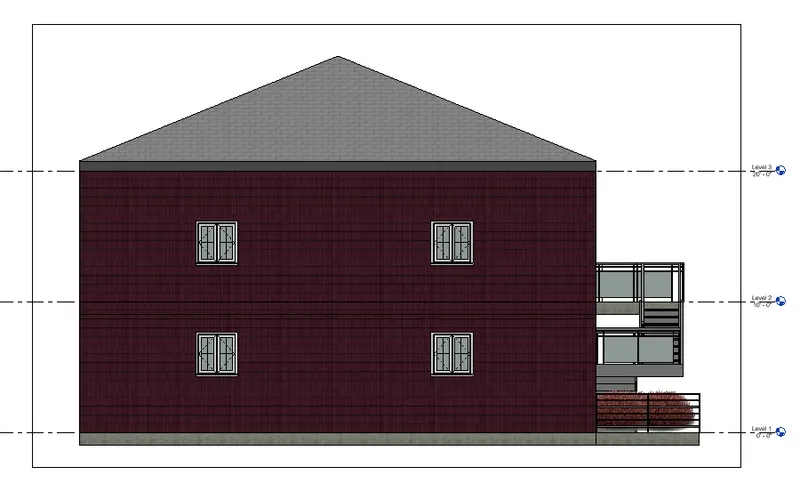
Result: Elevation views are created from the elevation tab
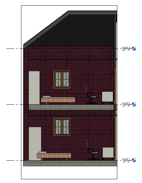
7. AIM: To produce section cut through each room either cutting across longitudinally or in a transverse direction.
INTRODUCTION:
- These views assume that a cutting plane has removed portions of the object represented by the drawing, displaying the appropriate section of the interior.
PROCEDURE:
Step 1:
Step 2:
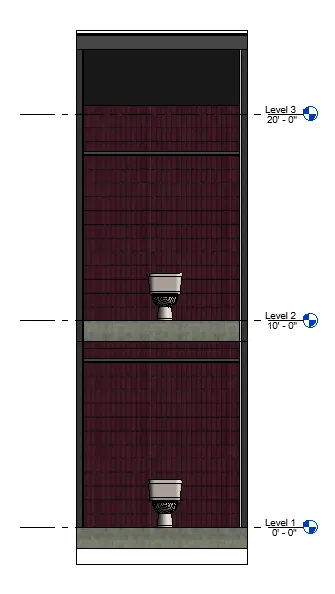
Step 3:
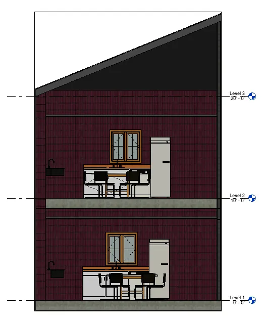
Step 4:
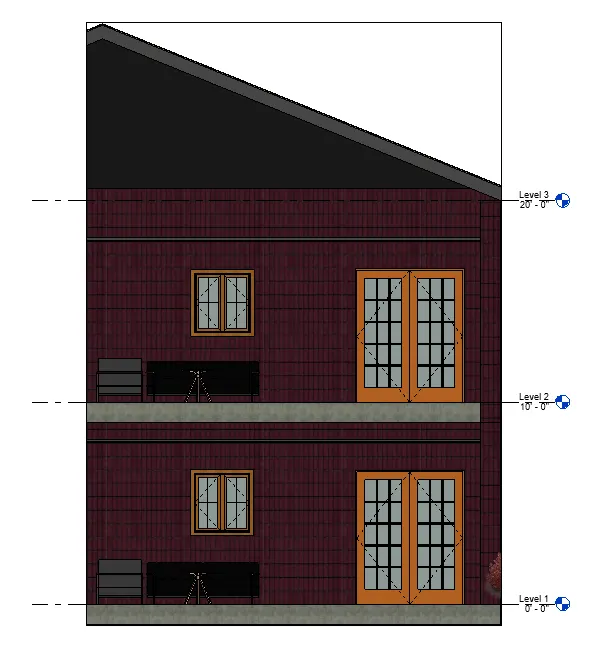
RESULT: Section views of a model is created
8. AIM: To classify the views, Plan Views, Section Views, and Elevation views to either Design or Documentation category using Properties browser.
INTRODUCTION:
- The structural plan view is the default view when you start a new project using a structural template.
- The floor plan view is the default view in a new architectural project
- Floor plan views are created automatically as you add new levels to your project.
- Sectional views reveal hidden details in a mechanical drawing.
- These views assume that a cutting plane has removed portions of the object represented by the drawing, displaying the appropriate section of the interior.
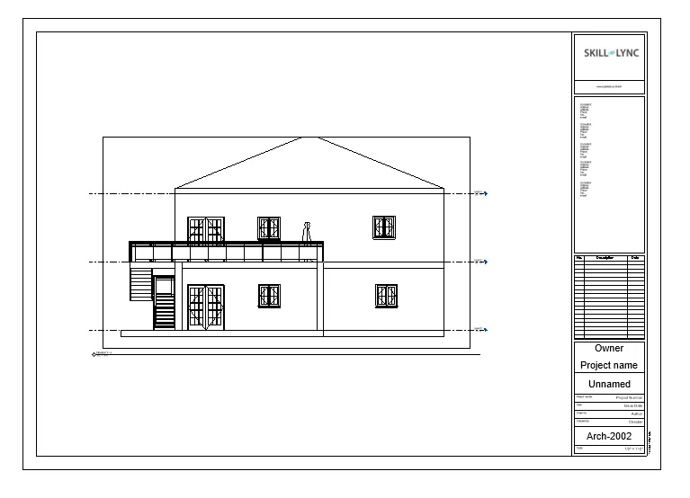
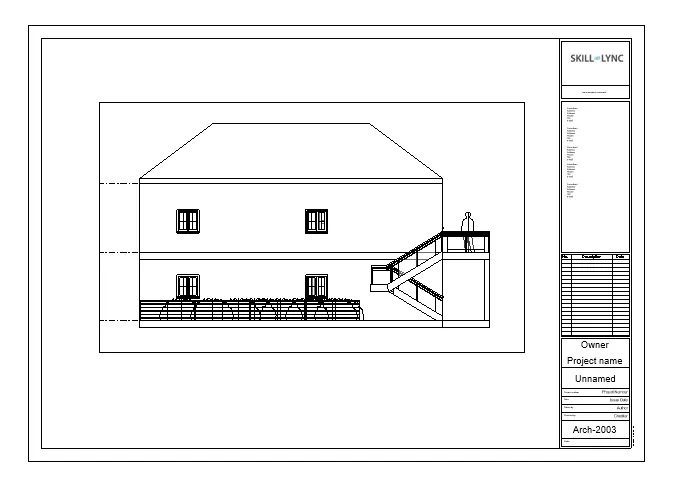
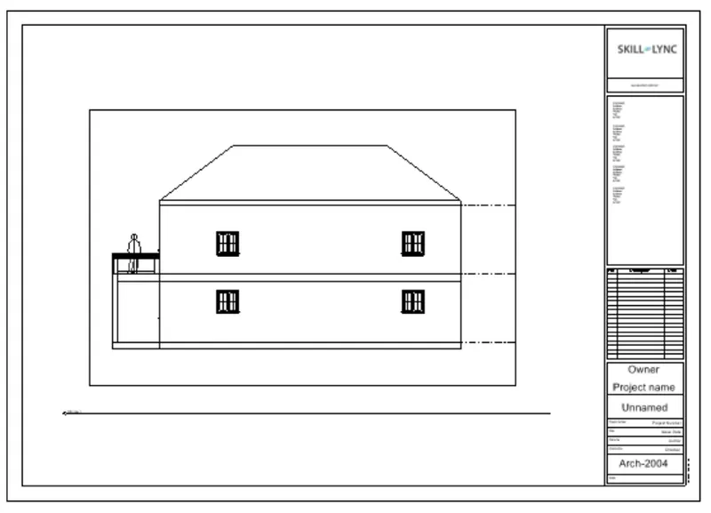
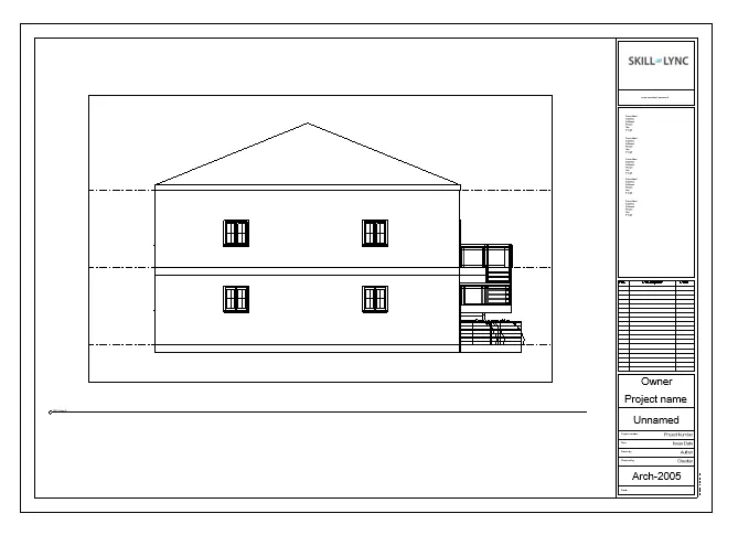
- An elevation is a view of a building seen from one side, a flat representation of one view.
- This is the most common view used to describe the external appearance of a building.
PROCEDURE:
Step 1:
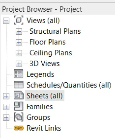
Step 2:
- Front elevation
Step 3:
- Left side elevation
Step 4:
- Right side elevation
Step 5:
- Back side elevation
Step 6:
- Ground floor plan
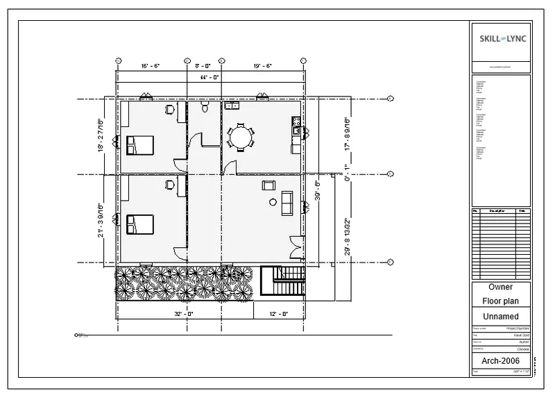
Step 7:
- First floor plan
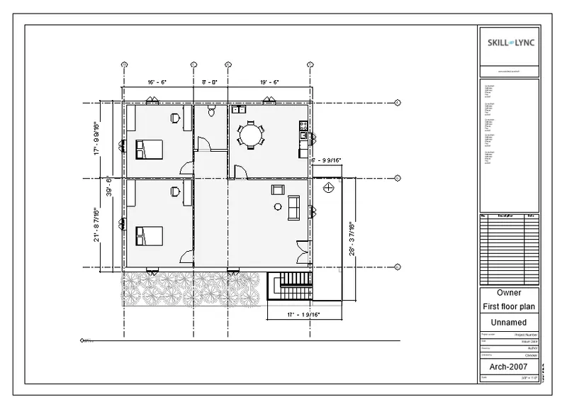
Step 8:
- Section-1
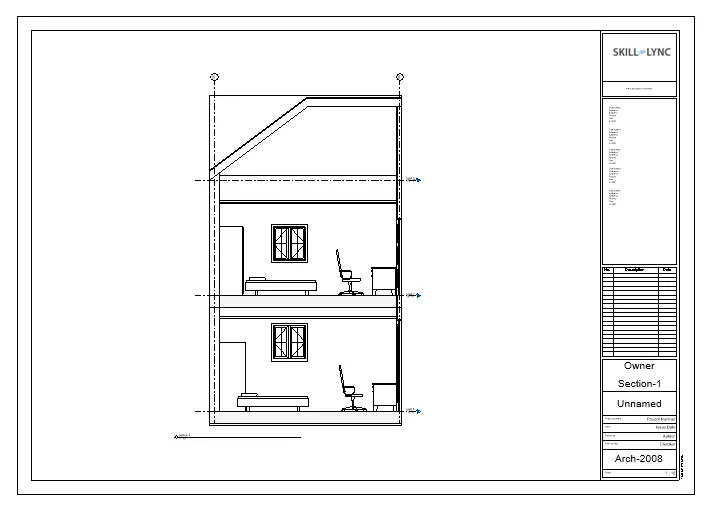
Step 9:
- Section-2
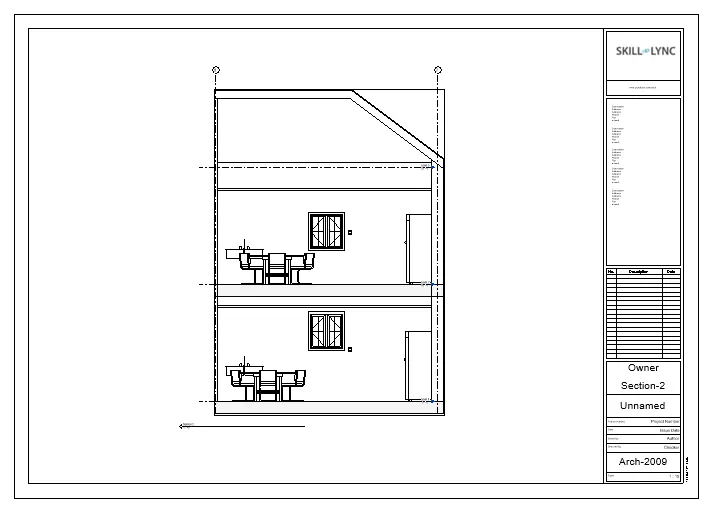
Step 10:
- Section-3
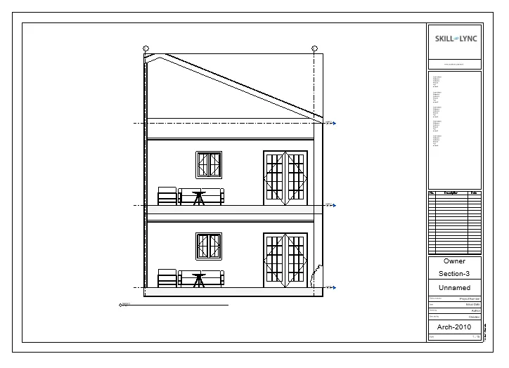
RESULT: Views, Plan Views, Section Views, and Elevation views are inserted in design category using Properties browser.
9. AIM: To create the multiple sheets and produce the drawings in the sheets, from the given drawing list.
INTRODUCTION:
- Create views on a project template before you start building the model
- When creating a project template, you can include sheets in the template
- Start with a blank project file, and create the standard views and levels.
PROCEDURE:
Step 1:
- Ground floor architectural plan in the sheet template A-101
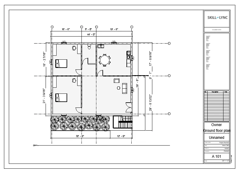
Step 2:
- First floor architectural plan in the sheet template A-102
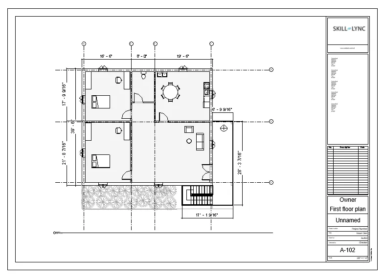
Step 3:
- Roof plan in the sheet template A-103
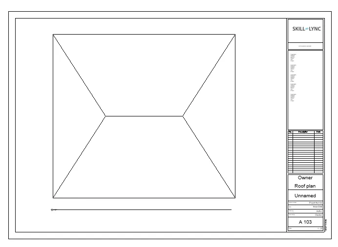
Step:-4
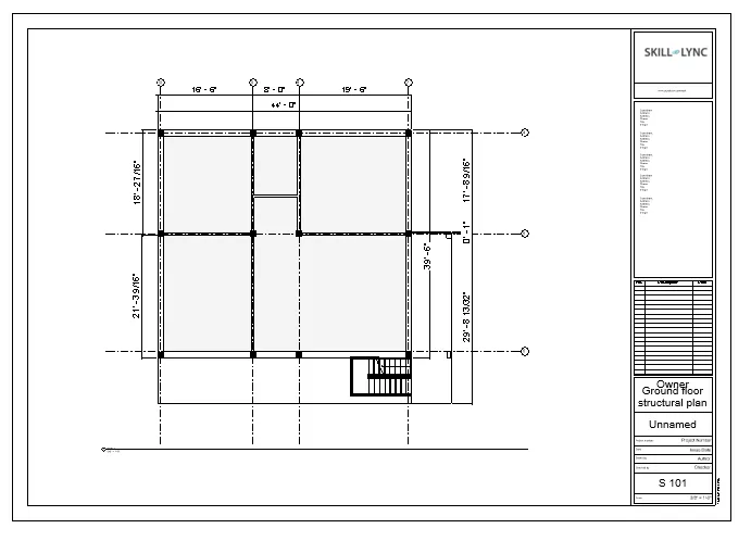
- Ground floor structural plan in the sheet template S-101
Step 5:
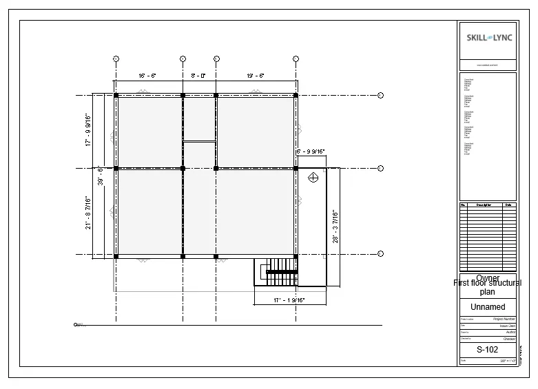
- First floor structural plan in the sheet template S-102
Step:-6
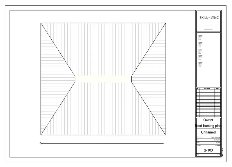
- Roof framing plan in the sheet template S-103
Step 7:
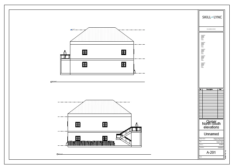
- North and south elevation views in the sheet template A-201
Step 8:
- East and West elevation views in the sheet template A-202
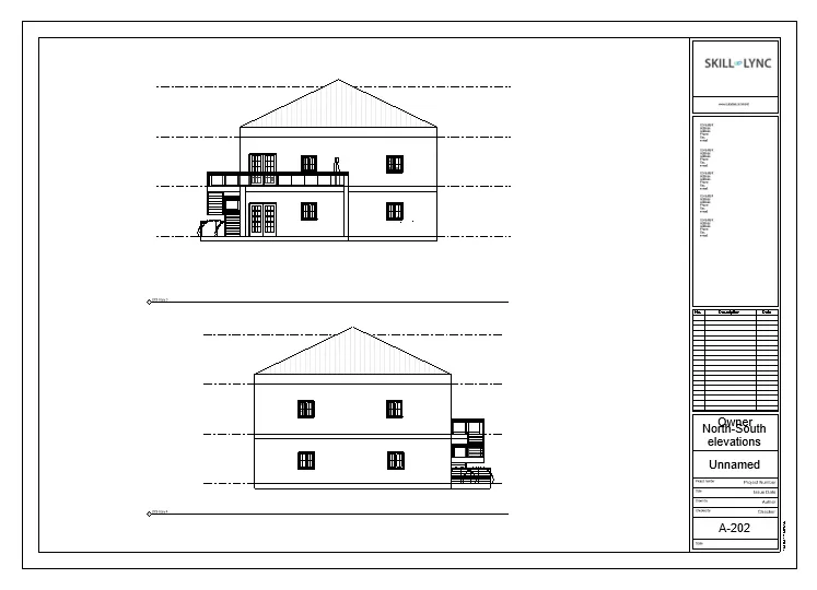
RESULT:
- Multiple sheets are created and produced the drawings in the sheets
10.AIM: To create a camera-specific view or a 3D view in living room, dining room and bedroom in the sheets separately.
INTRODUCTION: Camera Views are really useful in Revit.
PROCEDURE:
Step 1:
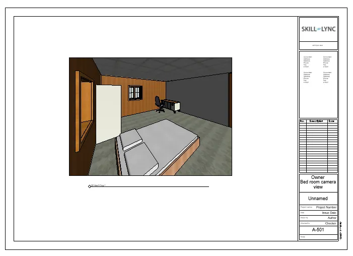
Step 2:
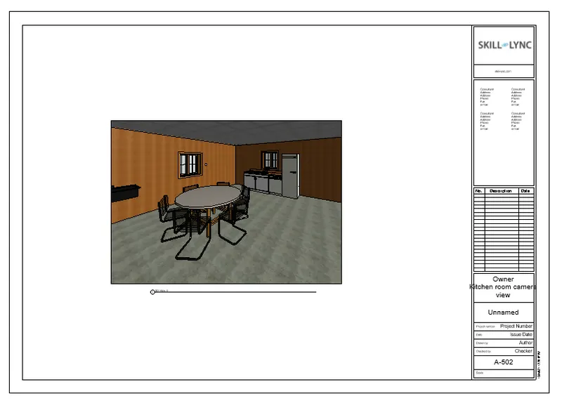
Step 3:
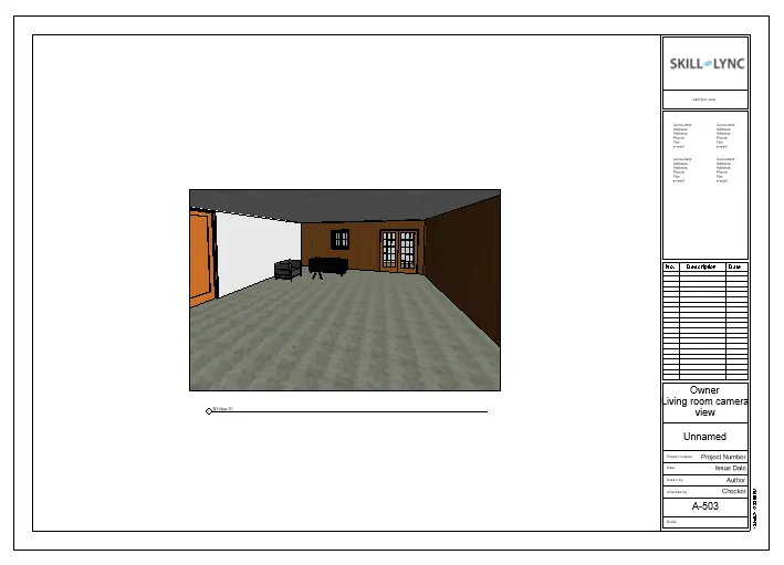
RESULT: Camera-specific view or a 3D view in living room, dining room and bedroom are created in the sheets separately.
Note: It is copied from Live session