3D Creation of Celing, Roof, Architectural plan, Structural plan, Sectional view, Elevation view and Camera specific view for a house plan using REVIT
1) AIM : Model a Ceiling from the architecture tab above the walls at the first-floor level.
INTRODUCTION : Based on project of week 3, i apply celing on level1 and level2. celing height is less than roof height.In the revit architecture, we can model celing by automatic celling or sketch celing.
i prefer celling by sketch.
PROCEDURE :
- First open the week3 project and go to first floor level of this project.
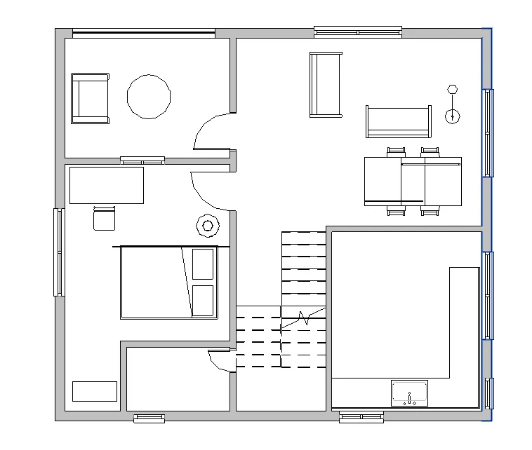
- now go to architecture tab ->celing->sketch celing->
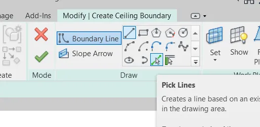
- now select pick lines and start selecting outer line of wall. And the boundary must be closed otherwise celing is not created.
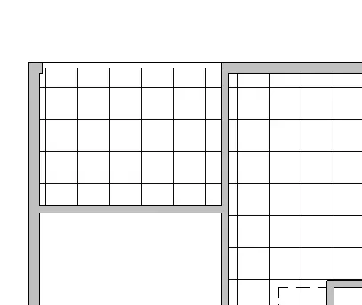
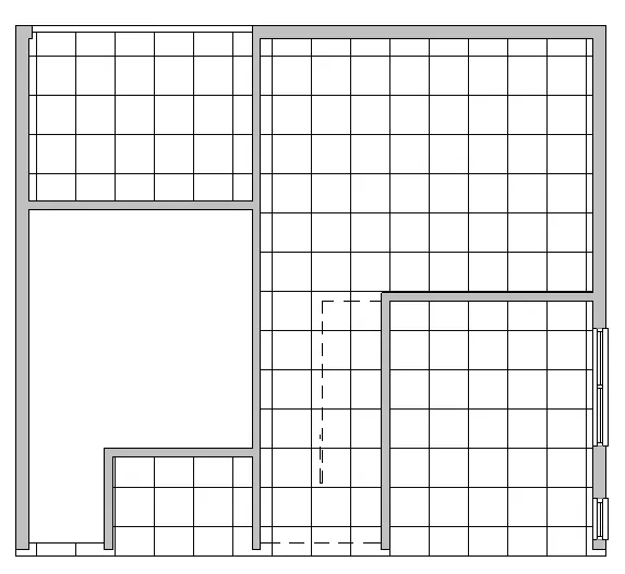
RESULT : CELING ON LEVEL1
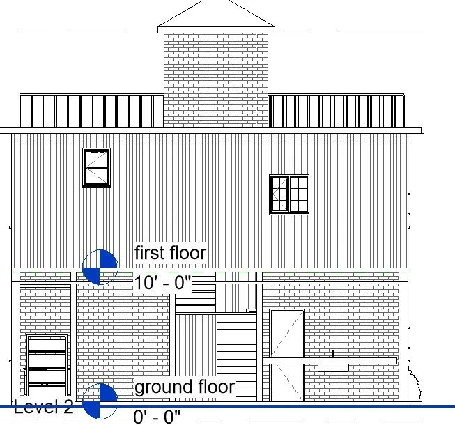
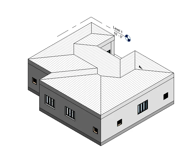
2) AIM :Model a roof above the ceiling by selecting the footprints of the ceiling.
INTRODUCTION : Based on project of week 3, we create roof using roof by foot print. It is very easy and best method to create roof on wall.
PROCEDURE :
- First open the week3 project and go to first floor level of this project.
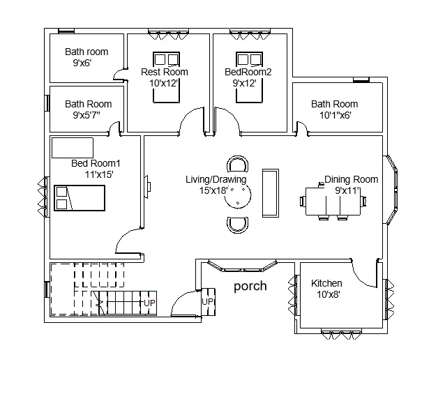
- go ro architectural tab => roof => roof by footprint
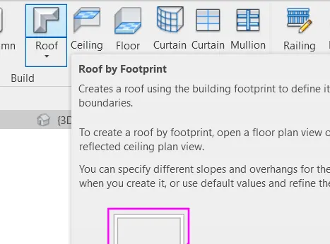
- now choose pick line and start selecting wall to which create roof
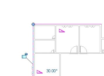
- now create roof on outer wall of building
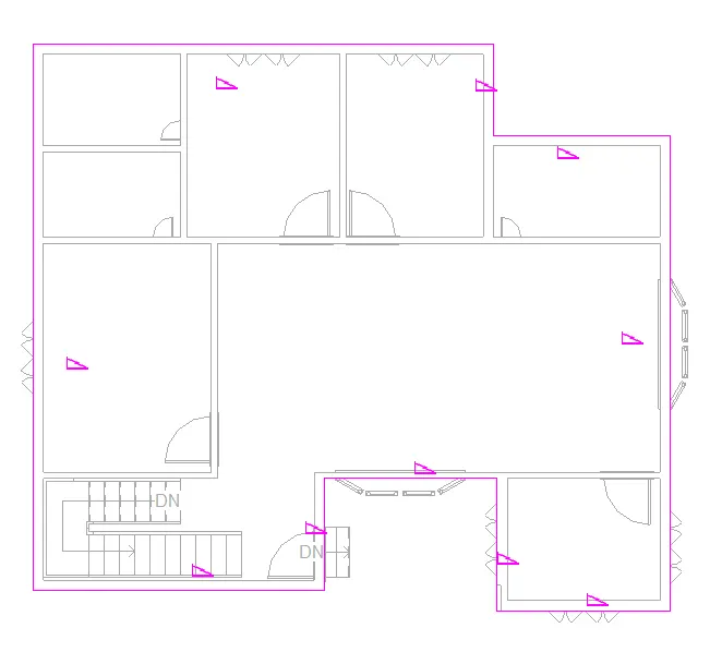
- before creating roof change the slope angle to 10 degree.
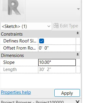
- after setting the value of slope and check any intersection points, click okk
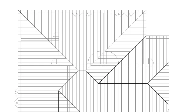
top view
RESULT :
3) AIM :create plan views for ground floor level and first-floor level including all the walls, floors, and components.
INTRODUCTION : Based on project of week 3, we create ground floor with wall,door, window and all components.But in first floor,we show the view as structural only show wall,column and floor.
PROCEDURE :
- First open the week3 project and go to ground floor plan
- Now go to plan view > strctural view and after that chhose leve1
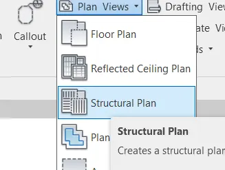
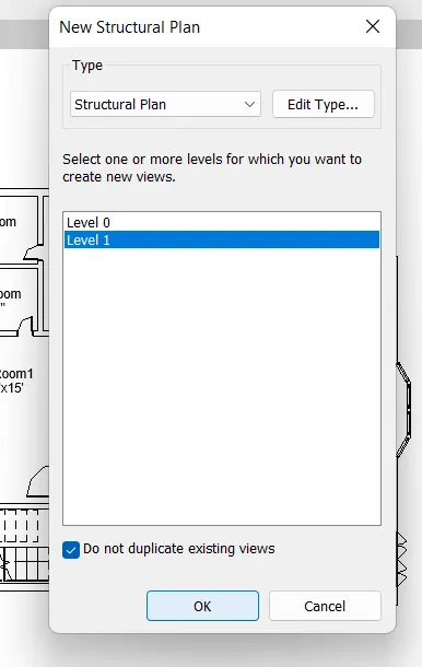
- now structural view
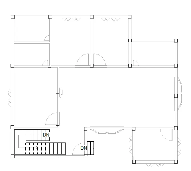
Result :
GROUND LEVEL (Architectural view) FIRST FLOOR(Structural view)
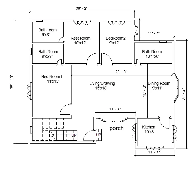
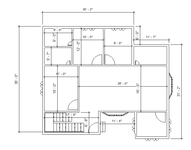
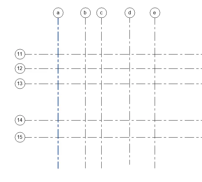
4) AIM :Using annotate toolbar add dimensions to all the walls and floors with reference to the longitudinal and transverse grids created in the project file
INTRODUCTION : Based on project of week 3, we already created floor plans.using that we use annotate tool bar
PROCEDURE :
- First open the week3 project and go to ground floor plan
- now go annotate tool bar> select aligned dimension
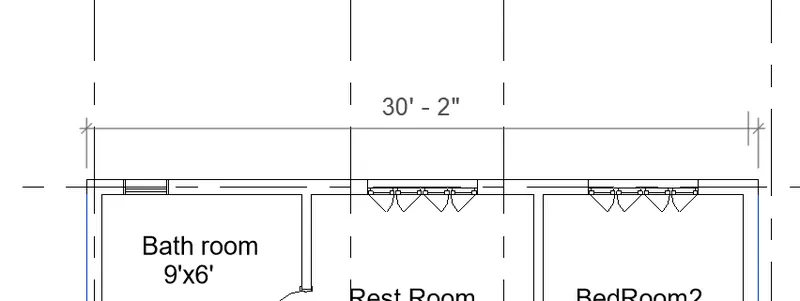
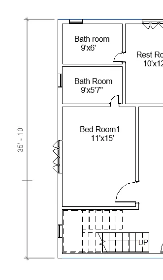
- now go to first floor structural plan and go to annotate tool bar and start dimensioning
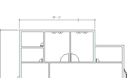
Result :
5) AIM :Create a sheet template from the view tab and adjust the parameters on the sheet to add appropriate views
INTRODUCTION : Based on project of week 3, we already created floor plans.
PROCEDURE :
- First open the week3 project and go to ground floor plan
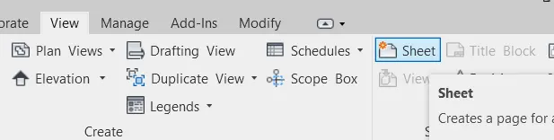
- now go to view tab and select sheet
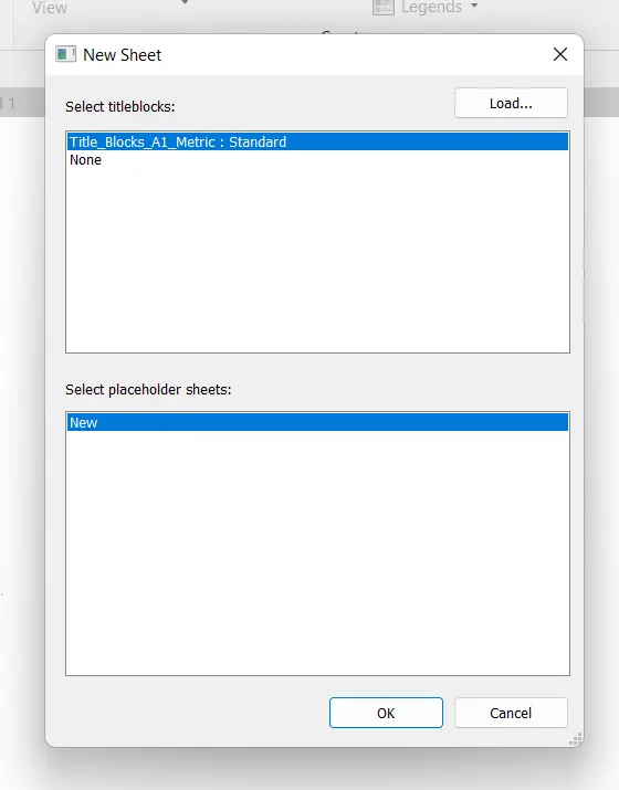
- now select type of sheet
- now just select view and drag it to sheet and adjust as per required
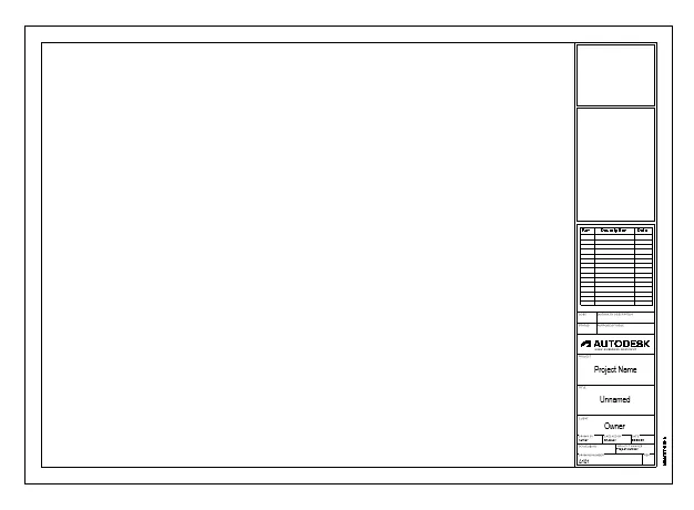
- Edit the tamplete as per required
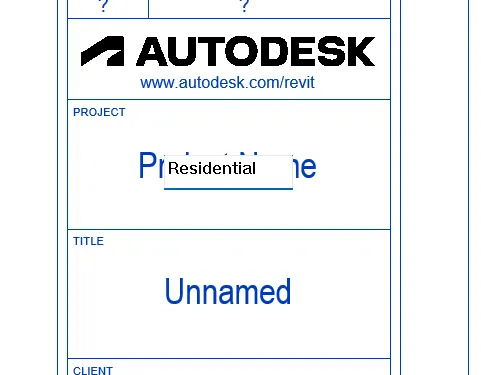
Result :
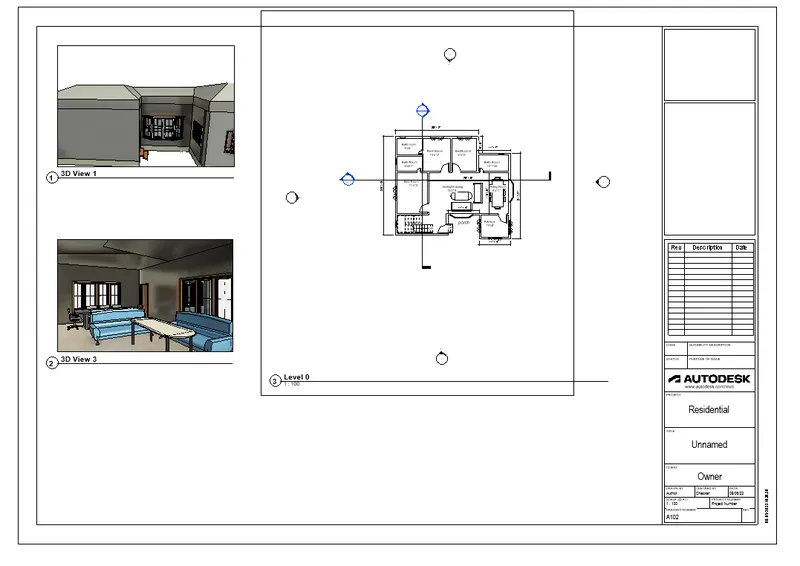
6) AIM :Using the elevation tab create the elevation views, looking at your building from East, North, South, and West.
INTRODUCTION : Based on project of week 3, we already created floor plans. Generally elevation view are alrady created.
PROCEDURE :
- first create floor plan after that go to project browser .Generally elevation view are already created in revit.If it is not created then go to view and after that go to elevation.
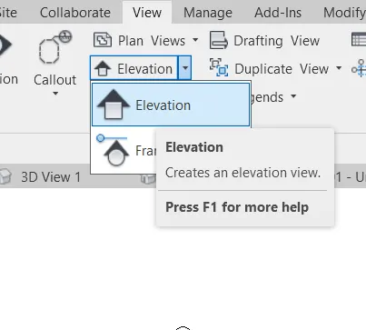
- In project browser,first go to east view
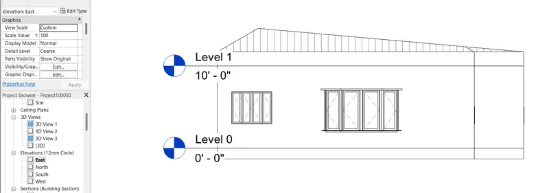
- In Project browser, go to north elevation view
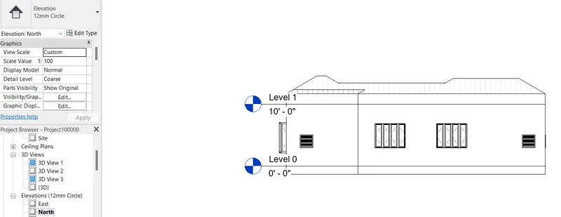
- In Project browser, go to south elevation view
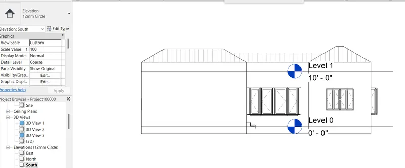
- In Project browser, go to west elevation view
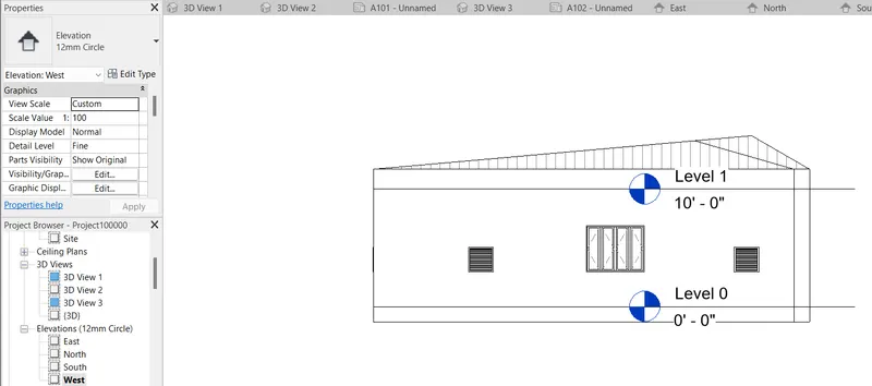
Result :
EAST NORTH
SOUTH WEST
7) AIM :Produce section cut through each room either cutting across longitudinally or in a transverse direction
INTRODUCTION : Based on project of week 3, we already created floor plans.
PROCEDURE :
- Go to view and select section view
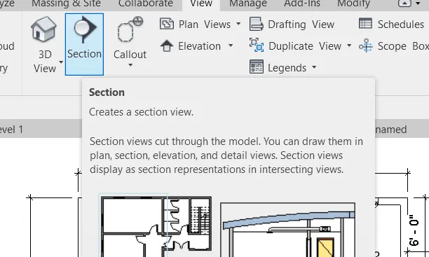
- now cut the floor plan in longitudinal and transverse direction
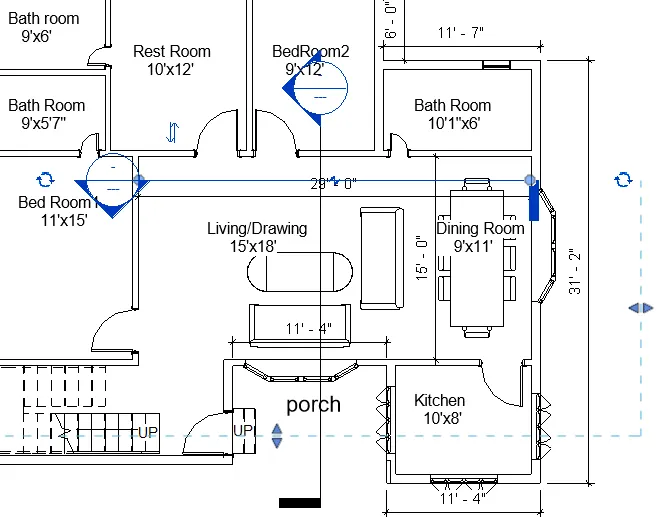
Result : Now go to project browser and click on section
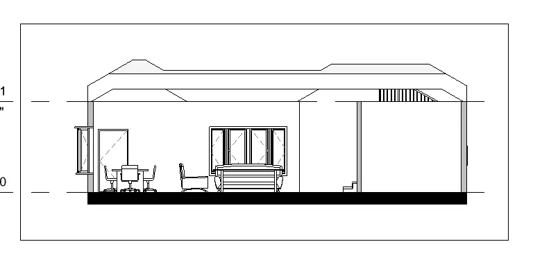
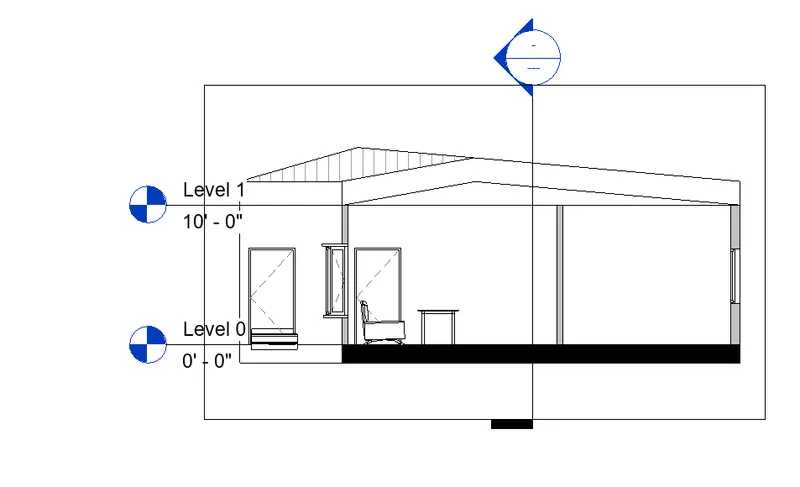
section -1 section-2
8) In project browser
- This is plan view.
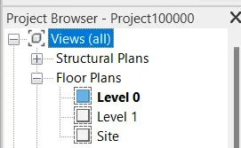
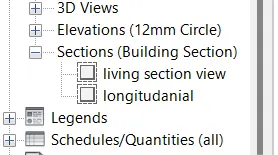
- This is section view
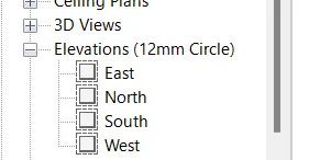
- This is elevation view.
9) Using the sheet template produced create multiple sheets
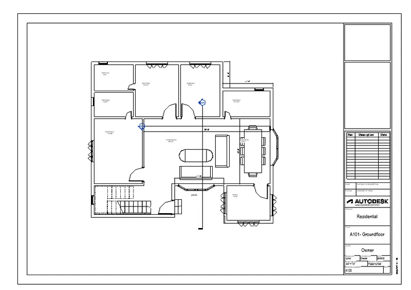
- A 101- Ground Floor Architecture Plan
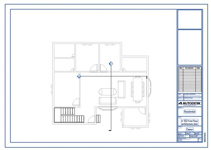
- A 102- First Floor Architecture Plan
- A 103-Roof Plan
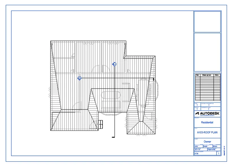
- S 101- Ground Floor structural plan
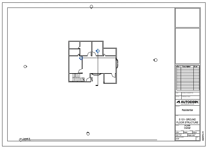
- S 102 - FIRST FLOOR STRUCTURAL PLAN
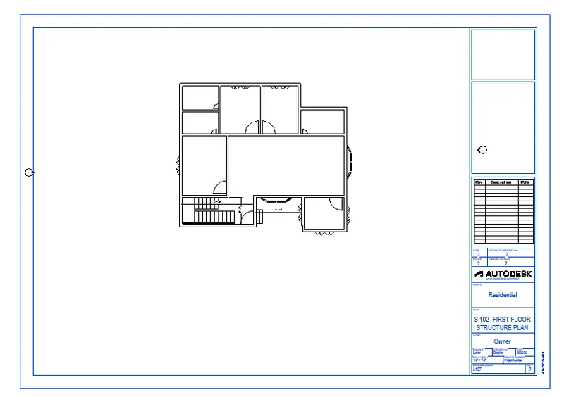
- S 103- ROOF PLAN
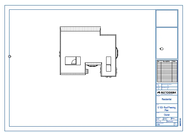
- A 201-North-South Elevations
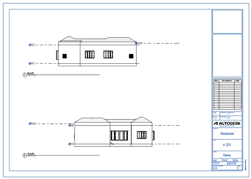
- A-202- East-West Elevations
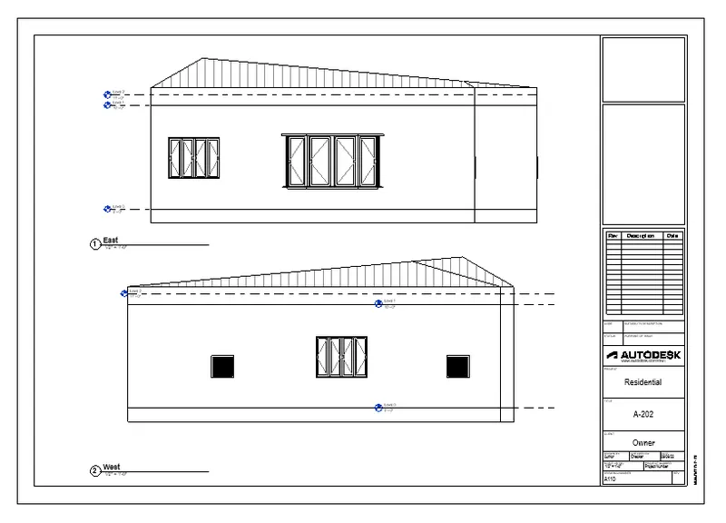
- SE-301 -SECTION Elevation
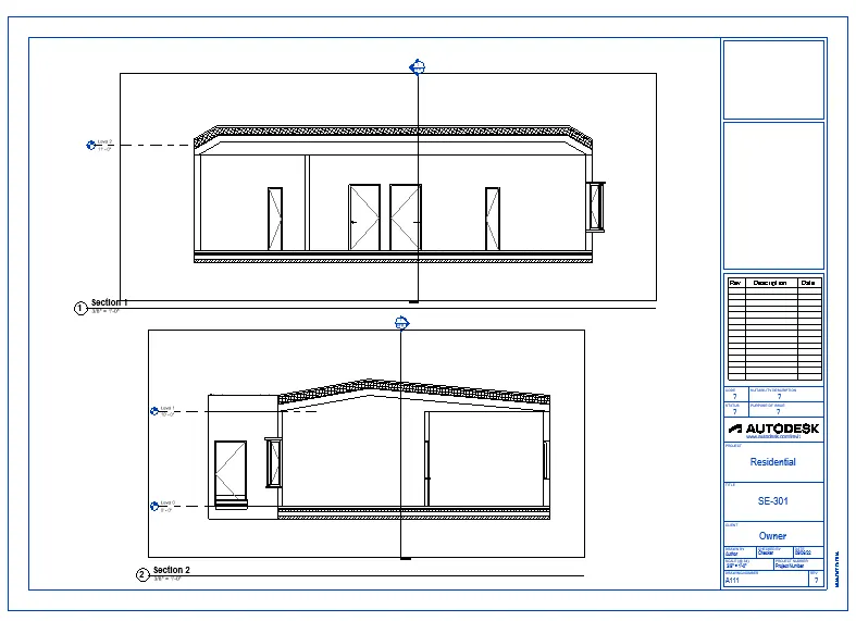
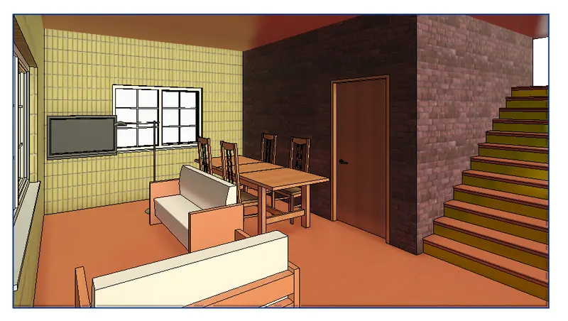
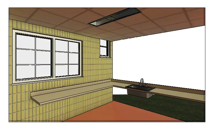
9) AIM- Create a camera-specific view or a 3D view in each room
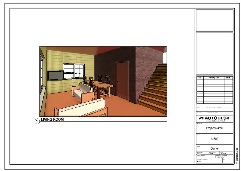
Introduction - Create a camera-specific view or a 3D view in each room ( living, dining, bedroom). Based on the views create a new set of sheets starting A-501.
PROCEDURE -
- go to view tab> click on camera
- go to ground floor and set camera on room
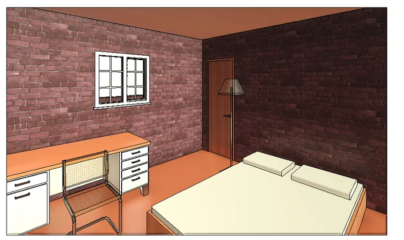
- Now set the camera in living room and dining room
- now set the camera on kitchen
- now create the sheet naming A - 501
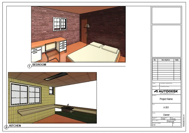
Result:
THANK YOU