3D Creation of Celing, Roof, Architectural plan, Structural plan, Sectional view, Elevation view and Camera specific view for a house plan using REVIT
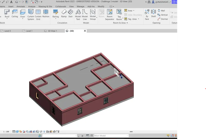
1. Aim: To model the ceiling element of the residential building for the floor level of the first floor of the week 3 challenge in the rivet soft ware.
- The ceiling is the layer below the roof of the residential building which is designed for the architectural purpose and to maintain the temparature shuffles which resist the hot temparature and makes the room cool condition.
- The ceiling is made of various materials and the ceiling is mostly commonly made with the gypsum boards.
Procedure:
- Click on the open option and select the challenge 3 model in the file menu click on OK then the file with the model formed in the challenge 3 is opened.
- Select the desired levelwhich we need to sketch the ceiling with the required thickness.
- Click on the architecture option in the ribbon and select the ceiling option and select the sketch ceiling and plot the celing in the required level.
- The ceiling material is editted to the desired material and the thickness of the ceiling is also changed to the required thickness from the properties browser in the window.
- The ceiling can be changed to the required thickness or material is eddited by the following steps.
- Click on the ceiling of the building model and select the ceiling of the building and now click on the edit type option in the properties browser.
- Now click on the structure edit option and it will shows the window to update the material and thickness of the ceiling.
- Click on the material category and select the material which we desired in the material browser and click on ok.
- Now the residential building with the desired ceiling material and the thickness is shown below.
2. Aim: To model the roof above the ceiling of the residential building for the floor level of the week 3 challenge in the rivet soft ware.
- The roof is top cover of the building which protects the inmates of the residential building from the weather conditions. The building is incomplete with out a roof.
- The roofs is of various types which may be flat roof or pitched roof. Pitched roof is mostly used in the areas where rainfall or snow fall is more.Flat roof is used where there will be more number of floors.
- The roof is made of various materials like concrete, AC sheets, GI sheets and in rare cases roof is made up of wood also.
Procedure:
- Click on the open option and select the challenge 3 model in the file menu click on OK then the file with the model formed in the challenge 3 is opened.
- Click on the architecture option in the ribbon and select the roof option and select the roof by foot print option and select the pick line option and plot the roof in the architectural model.
- The roof material is editted to the desired material and the thickness of roof is also changed to the required thickness from the properties browser in the window.
- The roof should have slope with a certain degree to drain the rain water or snow which falls on the roof,the degree of the roof can be changed.
- Click on the roof and in the properties browser change the degree of the roof and click on apply and the degree of the roof is changed.
- The roof material can be changed to the required thickness or material is eddited by the following steps.
- Click on the roof of the building model and select the roof of the building and now click on the edit type option in the properties browser.
- Now click on the structure edit option and it will shows the window to update the material and thickness of the roof.
- Click on the material category and select the material which we desired in the material browser and click on ok.
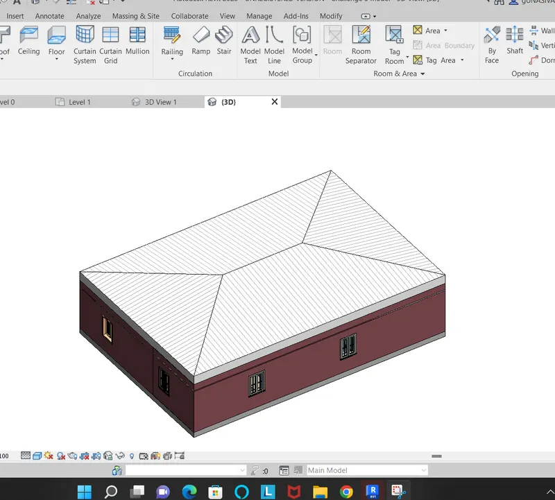
- Now the residential building with the desired roof material and the thickness with a particular degree is shown below.
3. Aim: To create the architectural and the structural view of the building of the week 3 challenge in the rivet soft ware.
- The model can be converted to various views which may be architectural or structural view. The architectural view refers the model outlet where as the structural view gives the full details of the columns or beams which are plotted in the residential model of the building.
- These views can be developed separately and we can view when ever required.
Procedure:
- Click on the open option and select the challenge 3 model in the file menu click on OK then the file with the model formed in the challenge 3 is opened.
- To develop various views of the model click on the views icon on the ribbon and select the plan view of the building and it shows the various options like floor plan,structural plan,ceiling plan,plan region etc for the model and select the required model option and click on the ok and the required model get displayed on the window.
- The views are developed to get to know the structure of the building model or to get to know about the architectural view of the building and to get know about the ceiling or to get to know about the plan region of the building.
- The architectural view develops the details of the rooms, furniture and walls and the doors,windows of the building where as the structural view develops the details of the columns or beams of the building.
- Now the architectural view and structural view of the residential building formed are shown below.
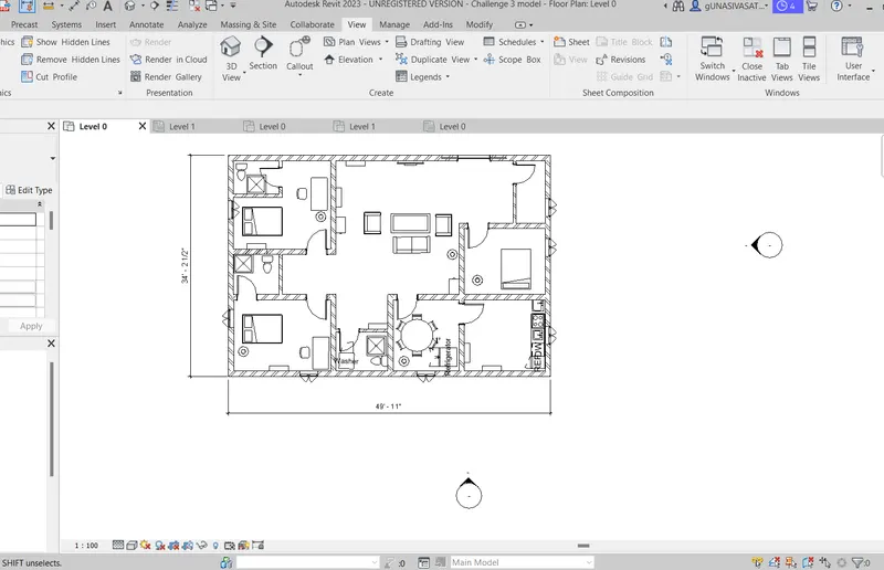
Architectural view
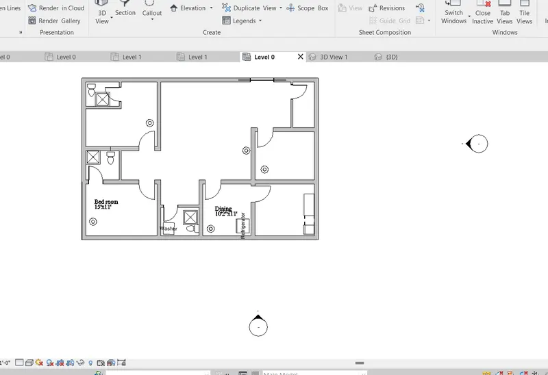
Structural view
4. Aim: To create the dimension for the architectural and the structural view of the building of the week 3 challenge in the rivet soft ware.
- The model can be converted to various views which may be architectural or structural view. But the dimension of the views may not be similar all the time so we need to create the dimension for the which are different to each other.
- After creating the dimension for the views the rooms sizes can be get know very easily with out any disturbance. The room sizes may vary from one level to other.
- The dimensions help to get to know the sizes of the room and it plays key role if there required any changes in the size of the room before the approval of the drawing.
- The dimensions of the architectural plan is distance between the walls where as the dimensions in the structural plan is the distance between the beams or the structural members in the plan.
Procedure:
- Click on the open option and select the challenge 3 model in the file menu click on OK then the file with the model formed in the challenge 3 is opened.
- The views which may be architectural,structural or ceiling view is formed from the plan view icon in the ribbon bar of the window.
- After creating the model of the building unit ,To develop the dimension of a particular view of the model click on the views icon on the ribbon and select the plan view of the building and it shows the various options like floor plan,structural plan,ceiling plan,plan region etc for the model and select the required model option and click on the ok and the required model get displayed on the window.
- Now enter VG command and some of the units in the model like Doors,Furniture may be hidden to avoid the overlap between the Dimension and the elements in the model.
- Now click on the Annotate bar and select the linear command in the ribbon and the dimensions is measured for the architectural or structural paln view of the building.
- Care should be taken to visible the dimensioning formed in the plan view of the building with out any overalp.
- Now the dimensions for the architectural and structural view of the building are formed as are shown below.
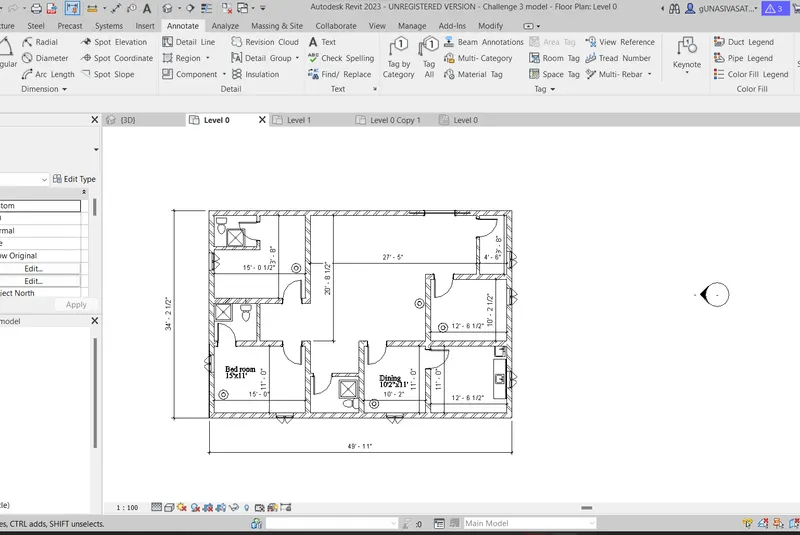
Architectural view
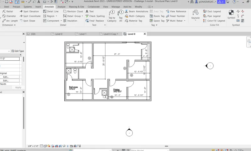
Structural view
5. Aim: To create the sheet for the submission of the drawing and to insert the drawing of a residential building of the week3 challenge in the rivet soft ware.
- The sheets are created to insert the particular view of the drawing to a required scale. A drawing is to be submitted after creating the sheet and inserting the required view in the sheet .
- After creating the sheet the drawing is to be insertedd and the details or schedules of the units in the building are also can be inserted in to the sheet.
Procedure:
- Click on the open option and select the challenge 3 model in the file menu click on OK then the file with the model formed in the challenge 3 is opened.
- The sheet can be created by clickin the view icon in the ribbon and select the sheet option,then a particular sheet is created with a specified name.
- The sheet contains various details like project name,name of the client and the details of the designer and the name of the checking person etc.
- Now the plan or the sectional view is inserted in the sheet for the submission to client.Click on the sheet option in the project browser and drag the particular view in to the sheet.
- The sheet of the view is formed with a particular scale, for the better view we can change the scale of the drawing in the sheet.select the drawing in the sheet and change the properties of the drawing from the properties browser.
- For the model created in the challenge 3 we can create the sheet for the architectural view and 3d model view.
- Click on the sheet inthe ribbon bar and then select the size of the sheet and click ok,now drag the architectural view to the sheet and also the 3d view is also dragged in to the sheet.
- The details of the project, client are entered in thesheet which gives the details of the drawing,these details can be entered either in the sheet itself or otherwise the details are entered in the project information option.
- The scale of the drawing in the sheet can be adjusted from the properties bar.
- The sheet created with the architectural view and the 3d model is shown below.
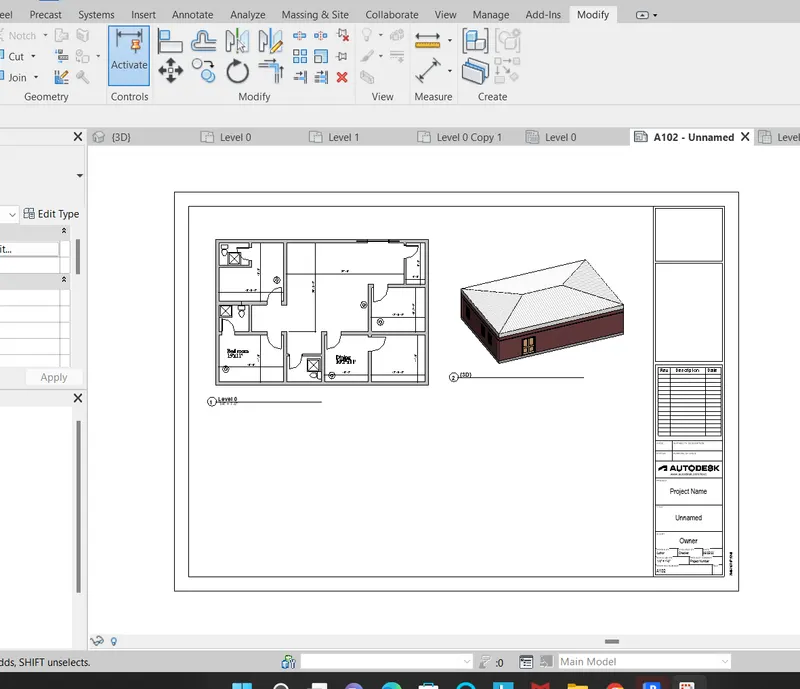
6. Aim: To create the elevation of the residential building created in the week 3 challenge in the rivet soft ware.
- Elevation is the outlook view of the building from the front or back or from the sides of the building.Elevation gives the information about the building length,width,height and also gives the details of the architectural appearence of the building.
- The Elevation gives the details of the various levels of the building i.e plinth level,floor finish level,lintel level,roof level etc and the level of the building are created or inserted only in the elevation view of the building.
Procedure:
- Click on the open option and select the challenge 3 model in the file menu click on OK then the file with the model formed in the challenge 3 is opened.
- The elevation view of the residential view of the building can be formed by clicking on the view tab in the ribbon bar.Select the floor level in the model and now select the elevation tab in the ribbon bar and now the ribbon bar is consisted with elevation option and select the elevation option.Click on the elevation option and an arrow mark is obatained at your cursor and place the arrow mark on the respective side i.e on the side or in the front or in the back side of the model.
- The arrow mark states the elevation view of the model,Now click on the elevation view in the project browserin the left of the window and there we can see the elevation views with the specified names i.e elavation A,Elevation B, ElevationC and ElvationD .
- The name of the elavation can also cahnged like front elevation,back elevation or side elevation of the building.
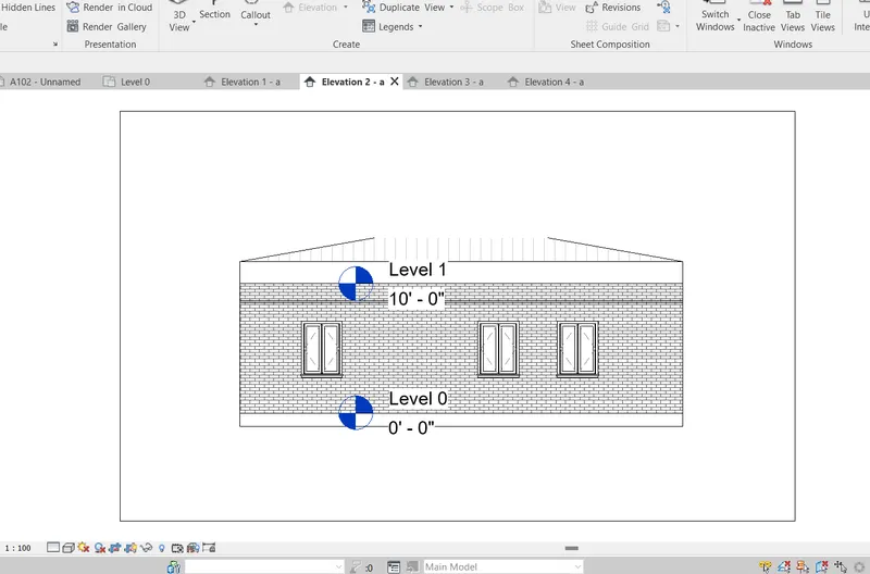
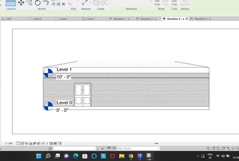
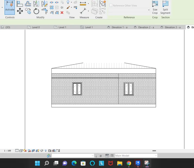
- The below model shows the elevation views of the building in all the four sides, The elvation shows the levels of the building i.e the floor level 0'0" and the slab level 10'.
- The elevation views formed for the residential building is shown below.
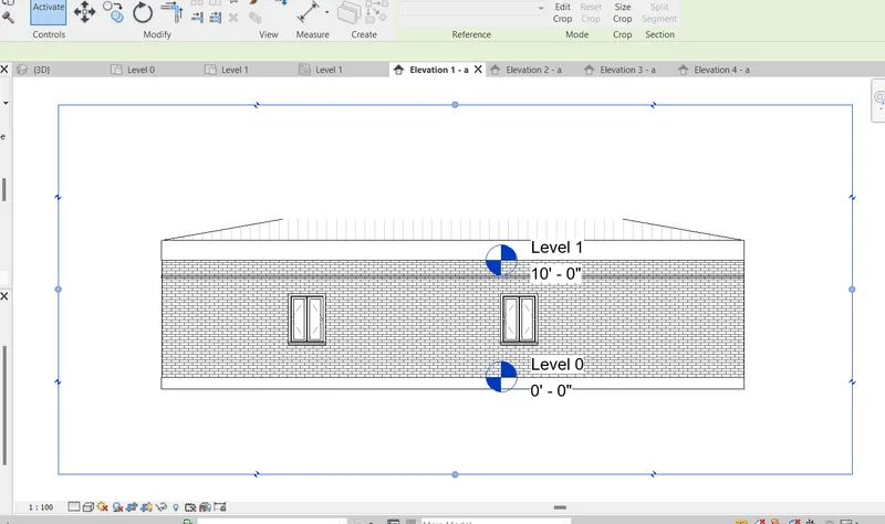
7. Aim: To create the section of the residential building created in the week 3 challenge in the rivet soft ware.
- Section is the view of the building fromed by cutting the building in a direction either transverse or longitudinally.It gives the inter details of the building when a cuting is paseed through it .
- The section is imporatnt to know about the internal profile of the beam, column,footing,door,window and any other unit in thebuilding model.
- The section gives the internal material profile of a building unit when a section line is paseed through the particular building unit.
Procedure:
- Click on the open option and select the challenge 3 model in the file menu click on OK then the file with the model formed in the challenge 3 is opened.
- The sectional view of the residential view of the building can be formed by clicking on the view tab tab in the ribbon bar.The section can be created in the floor level view of the model and the sectional view can be obtained in the project browser in the window.
- Select the floor level in the model and now select the view tab in the ribbon bar and now the ribbon bar is consisted with section option and select the section option.Click on the section option and draw a line on the floor plan in which the section is to becreated.After the plotting of the line the sectional view can be formed in the project browser.
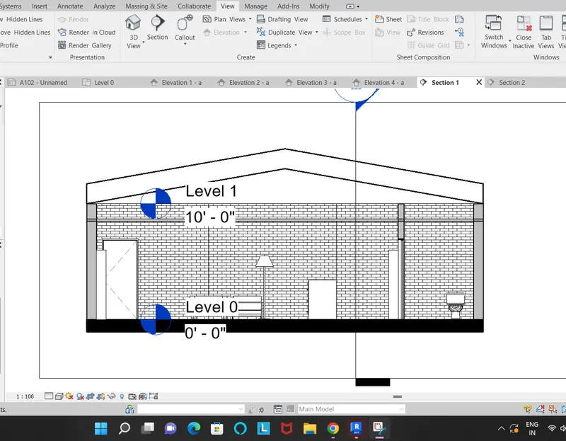
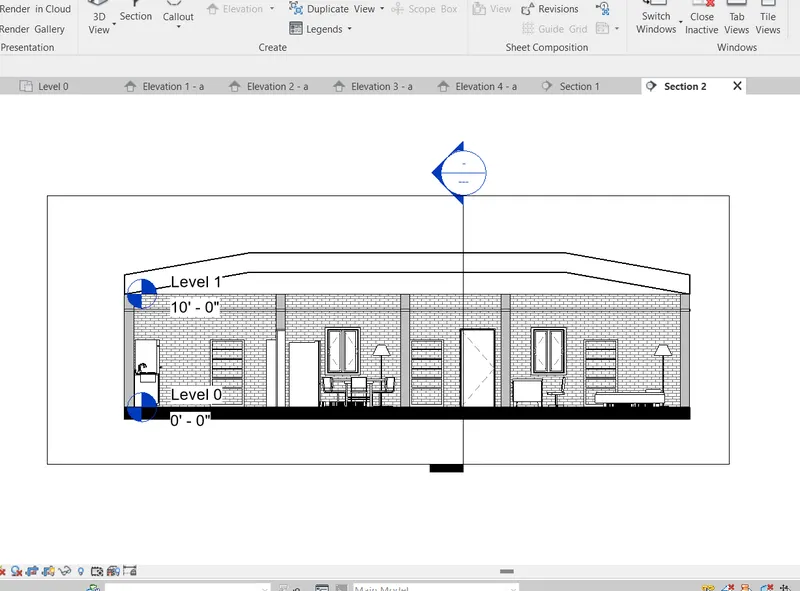
- Now click on the section view in the project browser and the section view is obtained with all the internal details of the building along the section lineplotted and it also gives the internal material properties of the building in which section line pased through nad we can also create number of section views according to the building design and building modelling.
- Section view also exhibits the details of the level of the building.
- The section view formed for the residential building is shown below.
8. Aim: To classify the various views of the building model in the rivet soft ware.
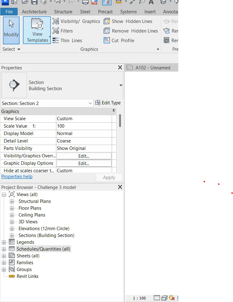
For a building model design we need to create the various views which gives the detail of the every element in the building very efficiently and in clear manner. Number of views in a particular project resembles the same building model design but exhibit the variuos details of the building.
The various views of the building model design are as follows:
- Structural plans: These are the plans at the various levels which exhibit the details of columns beams etc.It gives structural units of the building model.
- Floorl plans :These are the plans at the levels which gives the room details, furniture details and details of the building elements like doors,windows,ventilators etc.These are also known as the architectural plans.
- Ceiling plans: These are the plan which gives the details of the ceilng of the roof in the building. The ceiling is laid just below thw roof of thebuilding.
- 3d views: These are the views of the building in which the realistic view of thebuilding is exhibited in this views.
- Elevation views: These are the views which exhibit the architectural outlook appearence of the building.
- Sectional views:These are views formed by cutting a section in the building and it exhibit the interanal profiles of the building and also exhibit the material properties of the building.
- Schedules: The schedules are nothing but the details of doors, windows, columns,beams and any other building elements with various size and shape.
- Sheets:The sheets are developed with the project details for the approval for the client with all the schedules. A building model is incomplte with out the sheet creation.
- Families: These are the groups in a category for a particular building unit.Every building element consists of a sparate family.All the building elements in a project are inserted from their respective families.
These are various kinds of the views which we generally used in a project or building model design.
9. Aim: To create the sheet for the submission of the drawing and to insert the view of the residential building of the week2 challenge in the rivet soft ware.
- The sheets are created to insert the particular view of the drawing to a required scale. A drawing is to be submitted after creating the sheet and inserting the required view in the sheet .
- After creating the sheet the drawing is to be insertedd and the details or schedules of the units in the building are also can be inserted in to the sheet.
Procedure:
- Click on the open option and select the challenge 2 model in the file menu click on OK then the file with the model formed in the challenge 2 is opened.
- The sheet can be created by clickin the view icon in the ribbon and select the sheet option,then a particular sheet is created with a specified name.
- The sheet contains various details like project name,name of the client and the details of the designer and the name of the checking person etc.
- Now the plan or the sectional view is inserted in the sheet for the submission to client.Click on the sheet option in the project browser and drag the particular view in to the sheet.
- The sheet of the view is formed with a particular scale, for the better view we can change the scale of the drawing in the sheet.select the drawing in the sheet and change the properties of the drawing from the properties browser.
- For the model created in the challenge 2 we can create the sheet for the architectural ground floor,first floor ,structural ground floor,first floor etc
- Click on the sheet inthe ribbon bar and then select the size of the sheet and click ok,now drag the architectural ground floor view and again create another sheet and insert the architectural first floor to the sheet.In the same way we can create the sheets for all the views created for the residential building
- The details of the project, client are entered for each and every sheet which gives the details of the drawing,these details can be entered either in the sheet itself or otherwise the details are entered in the project information option.
- The scale of the drawing in the sheet can be adjusted from the properties bar.
- The sheets created with the various views of the residential building created in the week 2 challenge are shown below.
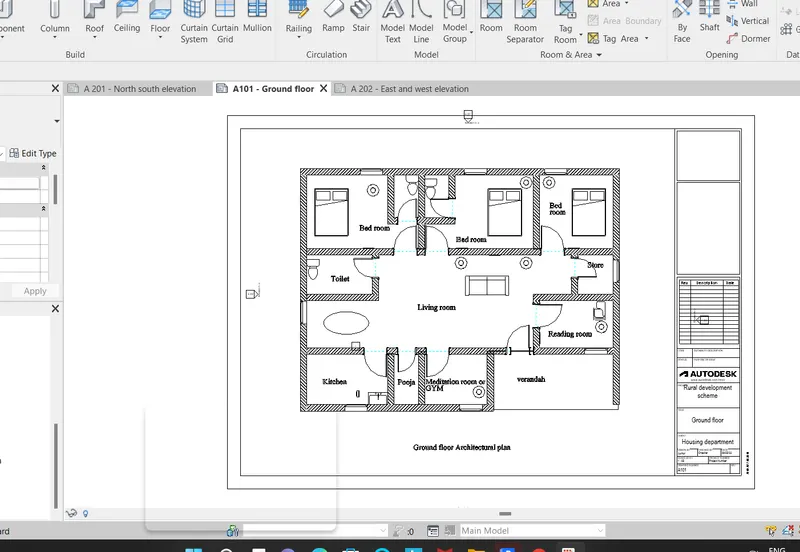
A101 Ground floor architectural plan
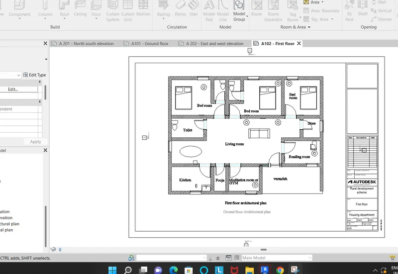
A102 First floor architectural plan
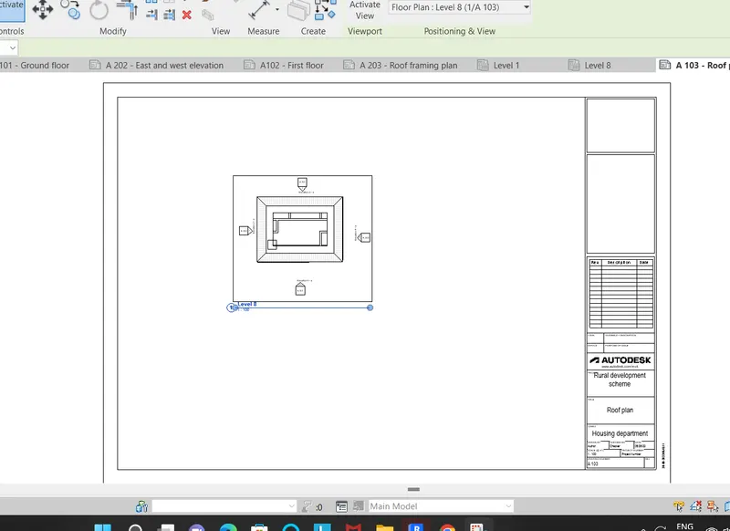
A103 Roof plan
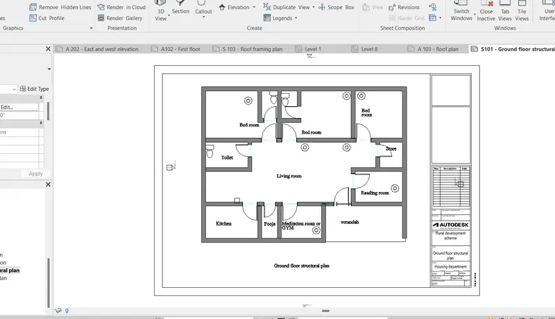
S101Ground floor structural plan
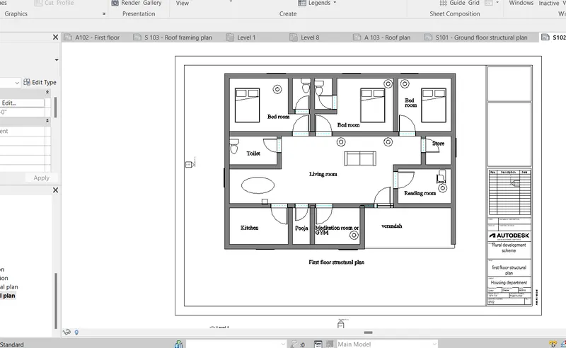
S102 First floor structural plan
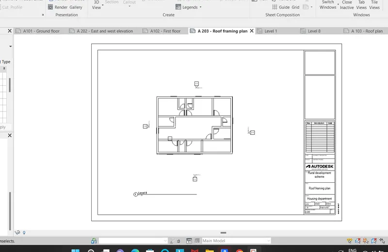
S103 Roof framing plan
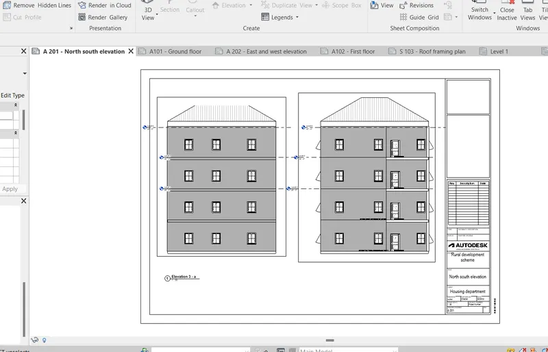
A201 North south elevation
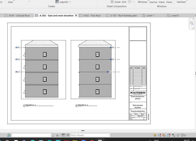
A202 East west elevation
10.Aim: To create the sheet for the submission of the drawing and to insert the camera view of the residential building of the week2 challenge in the rivet soft ware.
- The sheets are created to insert the particular view of the drawing to a required scale. A drawing is to be submitted after creating the sheet and inserting the required view in the sheet .
- After creating the sheet the drawing is to be insertedd and the details or schedules of the units in the building are also can be inserted in to the sheet.
- The camera view is the internal view of the building unit which forms the rendering view of the model.
Procedure:
- Click on the open option and select the challenge 2 model in the file menu click on OK then the file with the model formed in the challenge 2 is opened.
- The sheet can be created by clickin the view icon in the ribbon and select the sheet option,then a particular sheet is created with a specified name.
- The sheet contains various details like project name,name of the client and the details of the designer and the name of the checking person etc.
- The camera view can be created by the view tab in the ribbon in the window, select the ribbon and click on the 3d view and select the camera view and place the camera in the respective position at the rooms and the camera view is created in the project browser and the position of the camera is adjusted and the elevation of the camera can be editted in the properties browser.
- Now the camera view is created and inserted in the sheet for the submission to client.Click on the sheet option in the project browser and drag the particular view in to the sheet.
- The sheet of the view is formed with a particular scale, for the better view we can change the scale of the drawing in the sheet.select the drawing in the sheet and change the properties of the drawing from the properties browser.
- For the model created in the challenge 2 we can create the sheet for the camera view of the living room, dining room and bed room etc
- Click on the sheet inthe ribbon bar and then select the size of the sheet and click ok,now drag the camera view of the dining room and again create another sheet and insert the camera view of the bed roomto the sheet.In the same way we can create the sheets for the camera view of the living room created for the residential building
- The details of the project, client are entered for each and every sheet which gives the details of the drawing,these details can be entered either in the sheet itself or otherwise the details are entered in the project information option.
- The scale of the drawing in the sheet can be adjusted from the properties bar.
- The sheets created with the various camera views of the residential building created in the week 2 challenge are shown below.
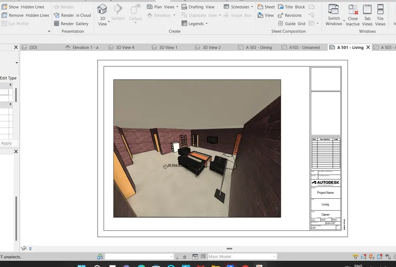
A501 living room
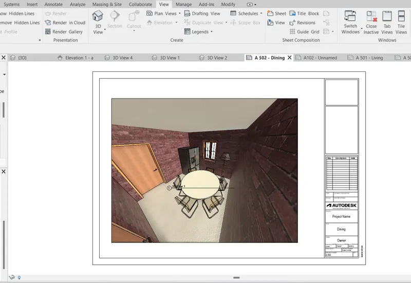
A502 Dining room
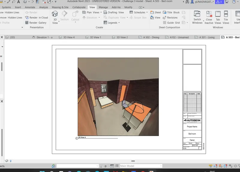
A503 Bed room