3D Creation of Celing, Roof, Architectural plan, Structural plan, Sectional view, Elevation view and Camera specific view for a house plan using REVIT
1.Based on the project saved from Week 3, proceed from the First Floor Level. Model a Ceiling from the architecture tab above the walls at the first-floor level
procedure:The creation of ceiling with in a revit family is a similar process to that of floors and roofs you can enter sketch mode & literarlly sketch out the boundaryof the ceiling.the main thing is to remember to be in the correct ceiling plan before start of revit.
step-1:First we open revit software and select ceiling option from architectural tab.
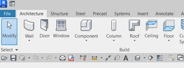
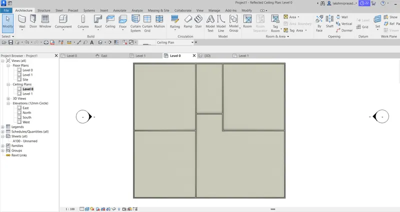
step-2: after selecting the ceiling option,then select each room one by one.then the ceiling will be created.
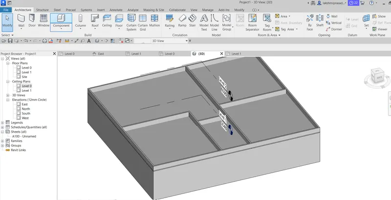
step-3: hence 3d ceiling design
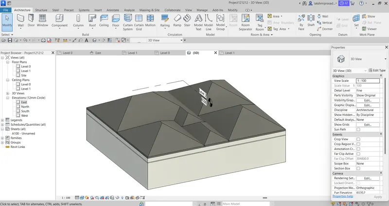
2.)Model a roof above the ceiling by selecting the footprints of the ceiling. Using the adjustment toolbars appearing on-screen adjust the roof slope to 10 degrees
procedure:Designing roofs in Revit can pose certain difficulties particularly for users less familiar with roof modeling tools. Creating exact roof geometry and size for a new build or modeling an existing roof to given dimensions is not always straightforward.
If we follow some key principles, however, we can model quite a few roofs simply by using Revit’s ‘Roof by Footprint’ tool. For more complex roof profile shapes, ‘Roof by Extrusion’ is typically used, which we will cover in future articles.
open the architecture tab and select roof and in that select roof by foot print.
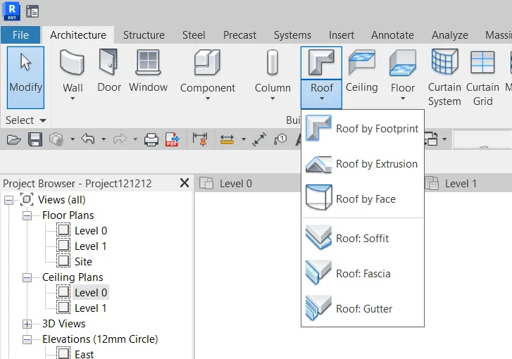
Step-2: Next we select the roof to 10 degrees by selecting,
3) Using the file saved from weeks 2 to 4, create plan views for ground floor level and first-floor level including all the walls, floors, and components. Separate them to
architecture and structural plans
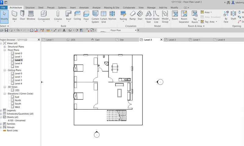
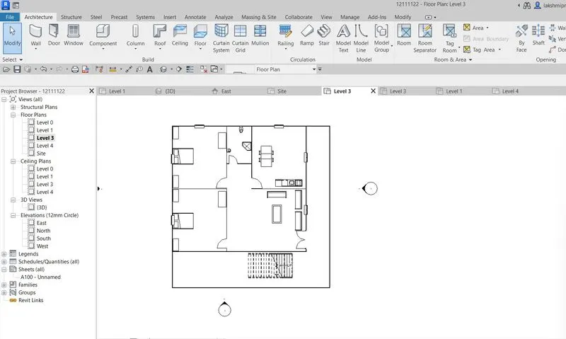
a. Architecture plan must have walls, floors, and all the components placed within the building
b. Structure plan must have details of only walls, floors, and columns.
Aim:to create Architecture plan must have walls, floors, and all the components placed within the building.
PROCEDURE: step-1:first we draw the architectural plan of the first floor-second floor as shown .
4) Using annotate toolbar add dimensions to all the walls and floors with reference to the longitudinal and transverse grids created in the project file
a. The architecture plan dimensions include details on where the components are placed within the buildings with relation to grids. Overall dimensions are sufficient for architecture plans
b. The Structure plan dimensions must include details on the position of all the walls and interior walls with reference to grids. Locate all the framing components of the building with reference to a fixed point using Structural plans
procedure:step -1:
hence we draw longituddnal & transverse grid to the architectural floor plan .
and add dimensons to the architectural floor plan.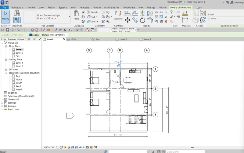
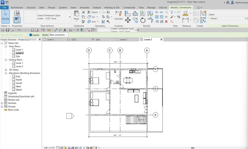
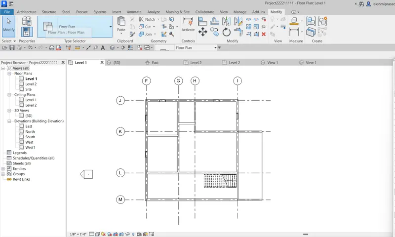
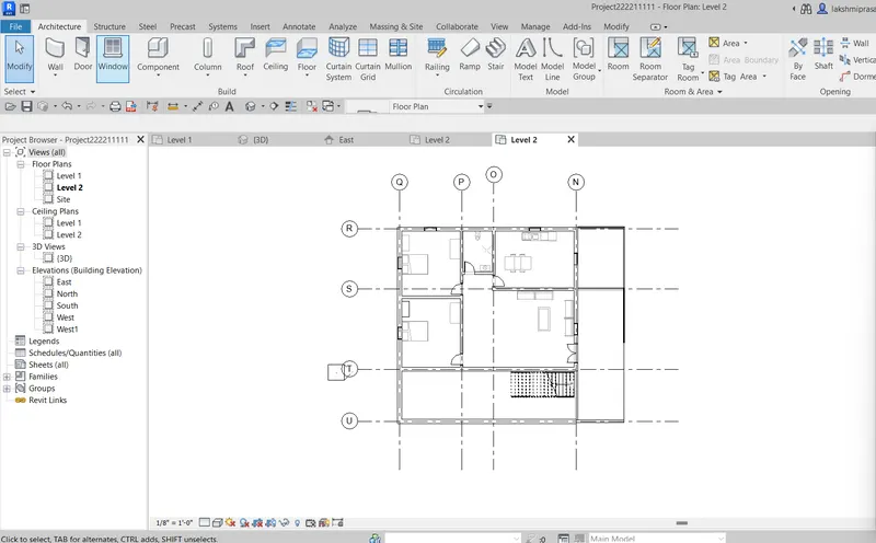
above two structural for design of ground floor & first floor level.
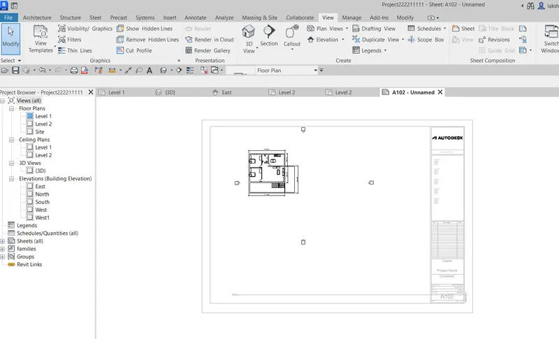
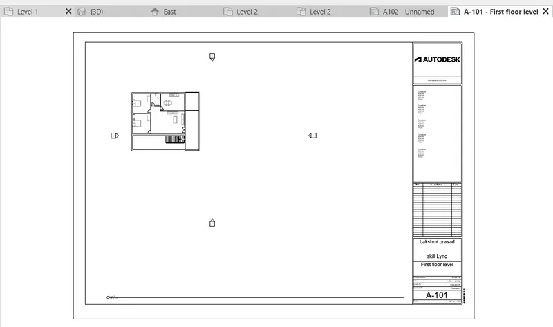
5.) Create a sheet template from the view tab and adjust the parameters on the sheet to add appropriate views
introduction:
A view template is a collection of view properties, such as view scale, discipline, detail level, and visibility settings.
Use view templates to apply standard settings to views. View templates can help to ensure adherence to office standards and achieve consistency across construction document sets.
Before creating view templates, first think about how you use views. For each type of view (floor plan, elevation, section, 3D view, and so on), what styles do you use?
For example, an architect may use many styles of floor plan views, such as power and signal, partition, demolition, furniture, and enlarged.
You can create a view template for each style to control settings for the visibility/graphics overrides of categories, view scales, detail levels, graphic display options, and more.
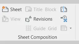
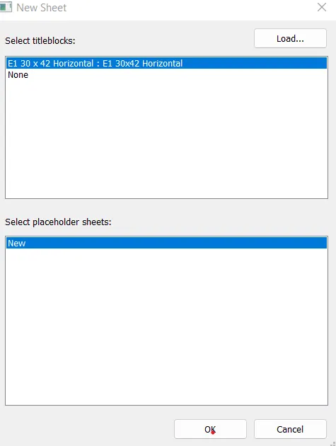
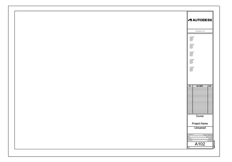
step-1: first click on sheet option from view tool bar. After clicking the sheet new tab will be visible on the screen.
6) Using the elevation tab create the elevation views, looking at your building from East, North, South, and West
- STEP 1 Open the project, and open [Level 1] floor plan
- STEP 2 Click [Elevation] from [View] tab, under [Create] panel
- STEP 3 Click the [Properties] palette > select Interior Elevation, the symbol will be updated.
- STEP 4 Hover over your plan. You will notice the elevation marker will “snap” parallel to walls. Please select the location where you want to place your elevation and click to set it in place. Press [Esc] to complete the command
- STEP 5 Select the elevation tag. You can create additional elevations from one elevation symbol. Press [Esc] to complete the command
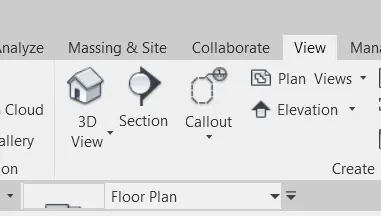
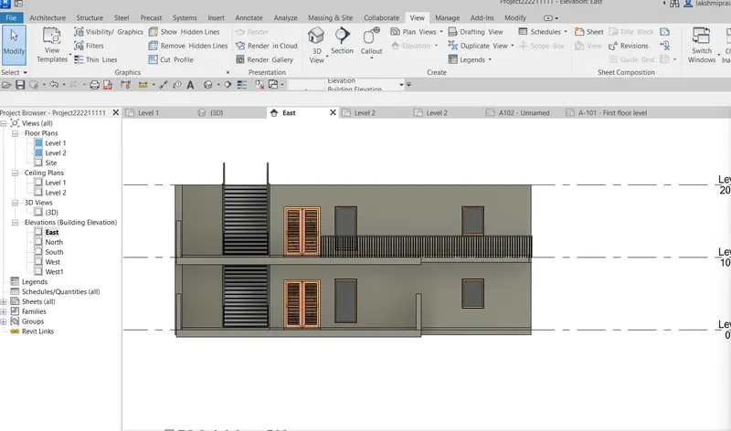
step-2:Next the elevaton from the east will be visible .
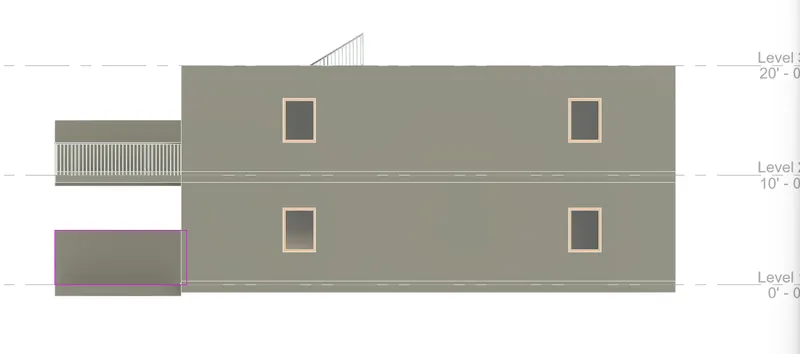
step-3:Next the elevaton from the north will be visible.
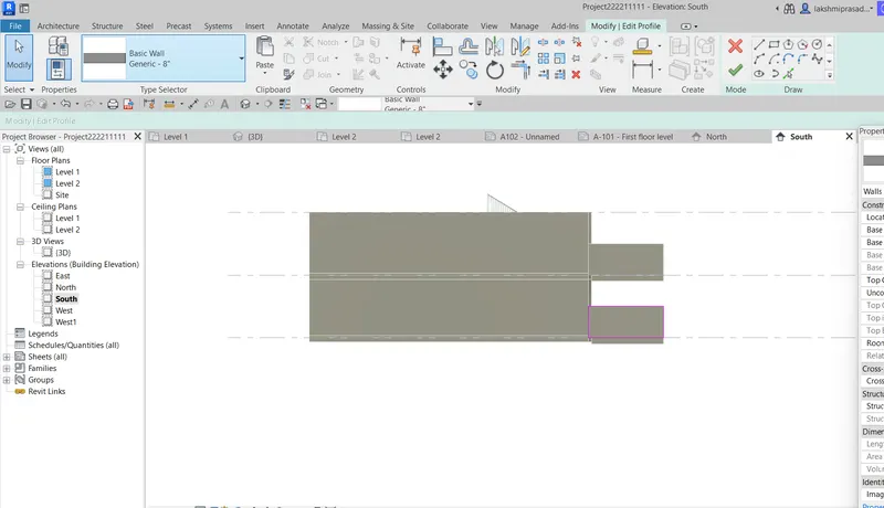
step-4:Next the elevaton from the south will be visible.
step-5:Next the elevaton from the west will be visible.
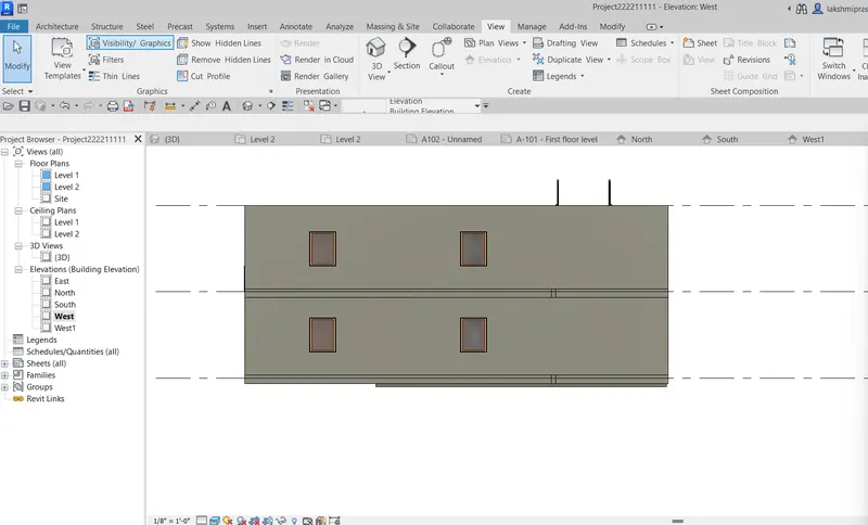
7) Produce section cut through each room either cutting across longitudinally or in a transverse direction
procedure: First we click on the section from the view tool bar. next we produce section of the bed room as shwn in fig:
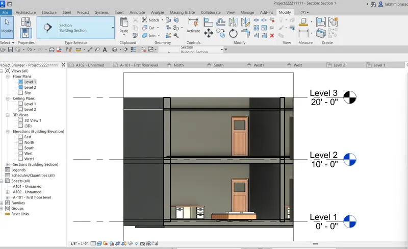
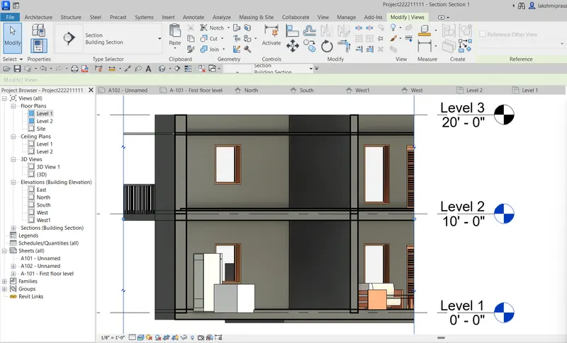
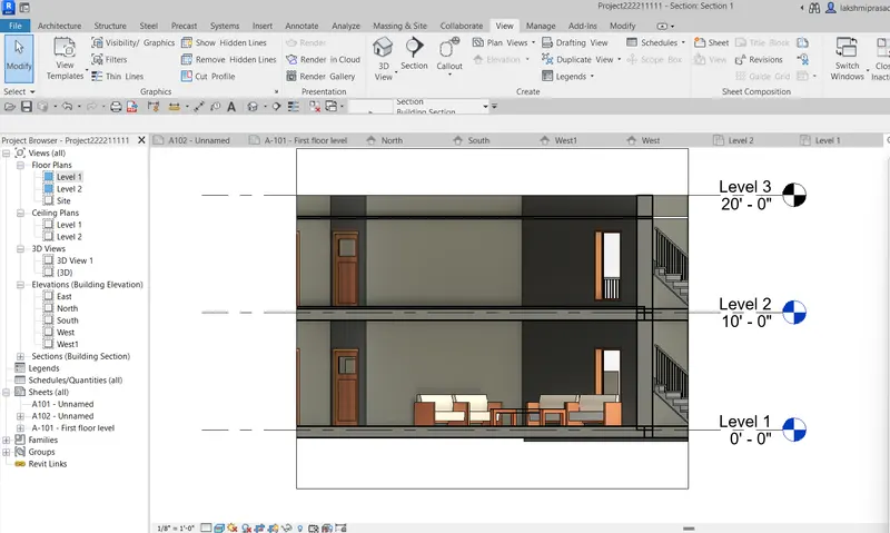
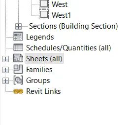
8.) Classify the views, Plan Views, Section Views, and Elevation views to either Design or Documentation category using Properties browser.
9.
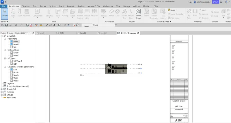
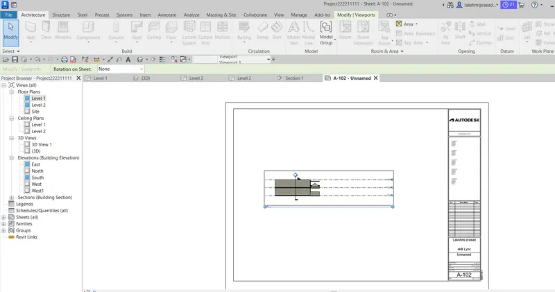
9) Using the sheet template produced create multiple sheets as follows
a. A 101- Ground Floor Architecture Plan
b. A 102- First Floor Architecture Plan
c. A 103- Roof Plan
d. S 101- Ground Floor Structural Plan
e. S 102- First Floor Structural Plan
f. S 103- Roof Framing Plan
g. A-201- North-South Elevations
h. A-202- East-West Elevations
Add additional sheets based on the sections created in your Revit file
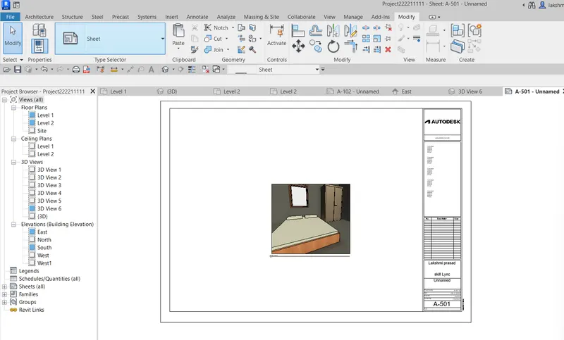
10Create a camera-specific view or a 3D view in each room ( living, dining, bedroom). Based on the views create a new set of sheets sta/)rting A-501 (you can add as many sheets after, 502, 503.. n)to place the 3D view images. Produce the sheets as a part of project drafting.
procedure :
bedroom :
kitchen view.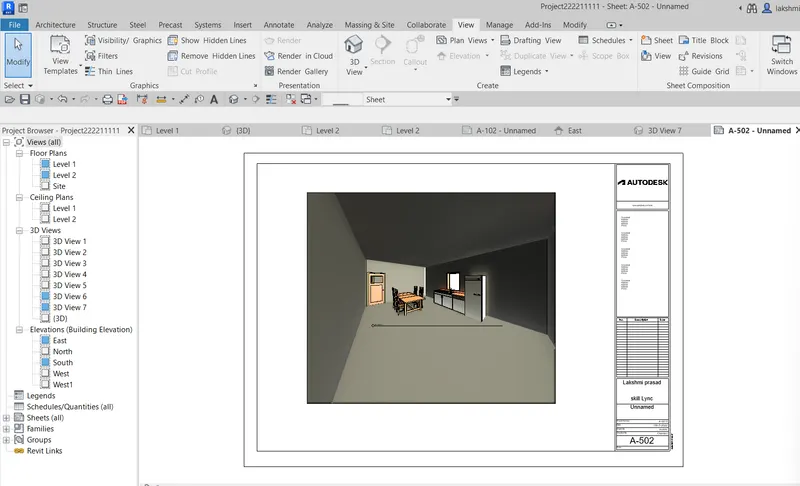
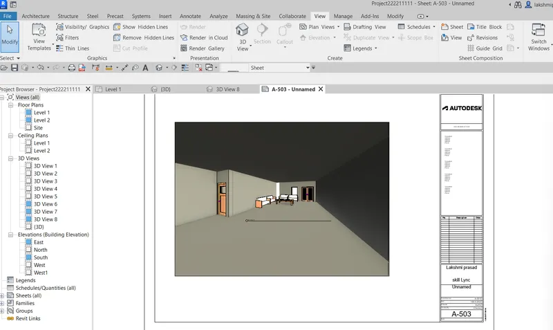
above one hall view.