3D Creation of Celing, Roof, Architectural plan, Structural plan, Sectional view, Elevation view and Camera specific view for a house plan using REVIT
1.Aim & Introduction
Aim
This challenge aims to allow the student to utilize and understand the Revit software tools and parameters. It familiarizes the student to the Revit modeling and drafting that includes the creation of all elements in a sketch such as Grid Lines, Levels, Architectural elements, Strctural elements, and structural Parameters
Intruduction
Revit is a building information modeling software that allows the user to create and design a 3D model building structure. It is an architectural,strcutural, and mechanical software where the user can provide 3D illustration of the building as well as its design
2. Detail Procedure
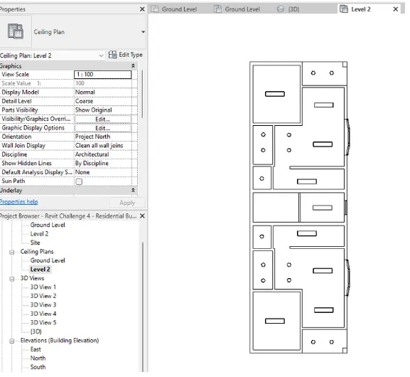
1) Based on the project saved from Week 3, proceed from the First Floor Level. Model a Ceiling from the architecture tab above the walls at the first-floor level
Ans:
PROCEDURE:
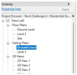
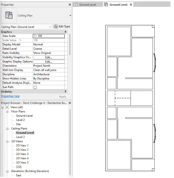
- Go to ceiling plan
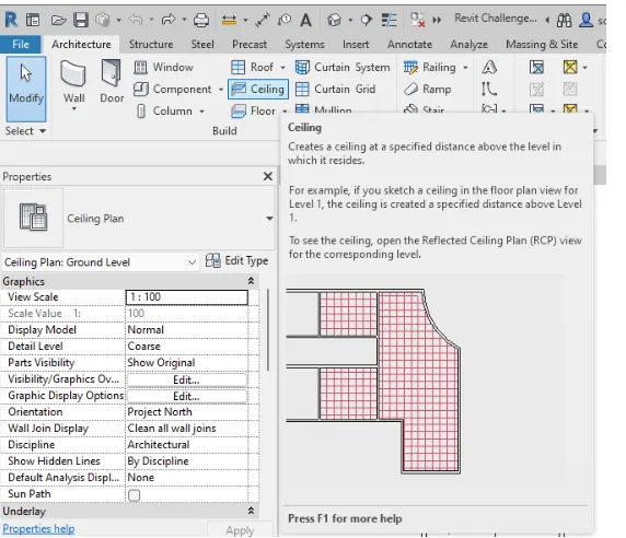
- Select the ceiling tool from the Architecture tab and add the ceiling
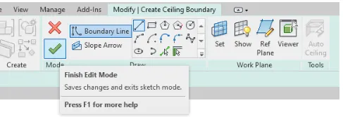
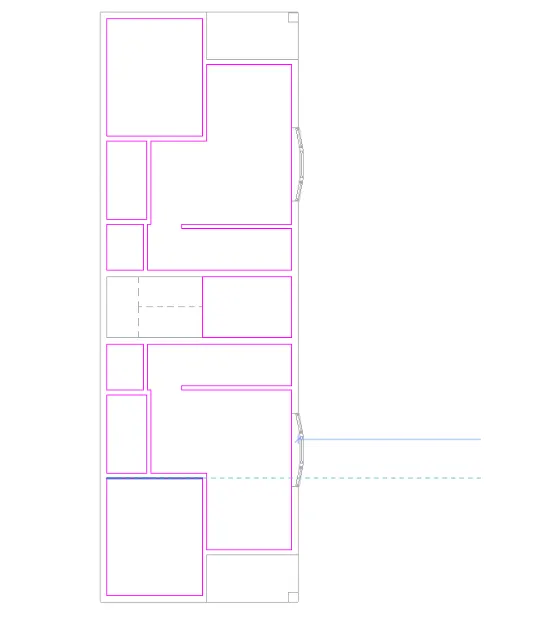
- Once the ceiling is placed, add the lighting components
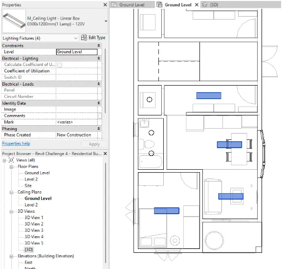
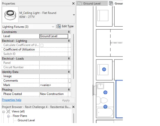
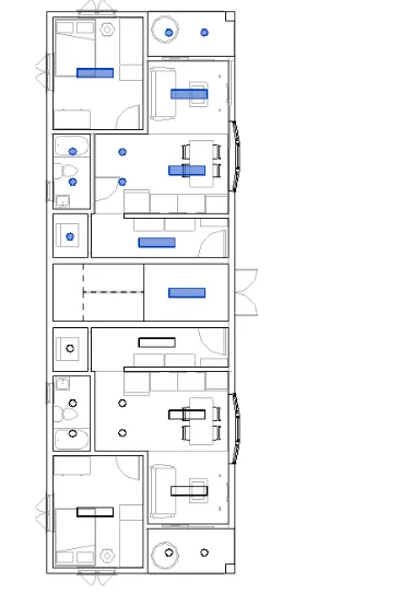
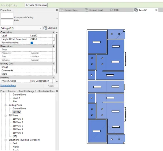
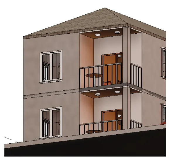
- Go to 3D view and make sure the ceiling is in the right position
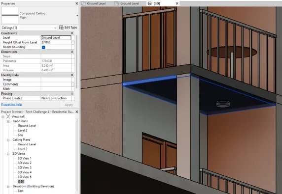
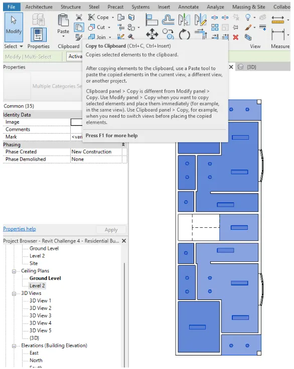
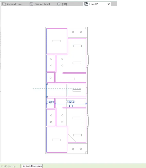
- When the position is correct, copy all ceiling elements to the floor
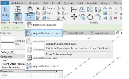
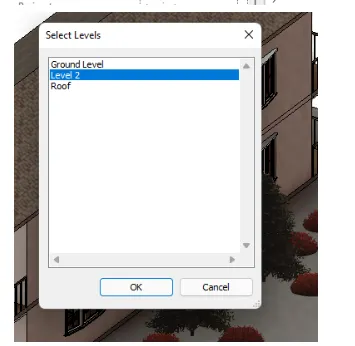
- Adjust to desired location and edit boundary
2) Model a roof above the ceiling by selecting the footprints of the ceiling. Using the adjustment toolbars appearing on-screen adjust the roof slope to 10 degrees
Ans:
PROCEDURE:
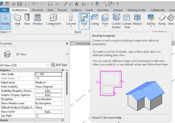
- TO add the roof, go to Architecture tab and select the roof tool
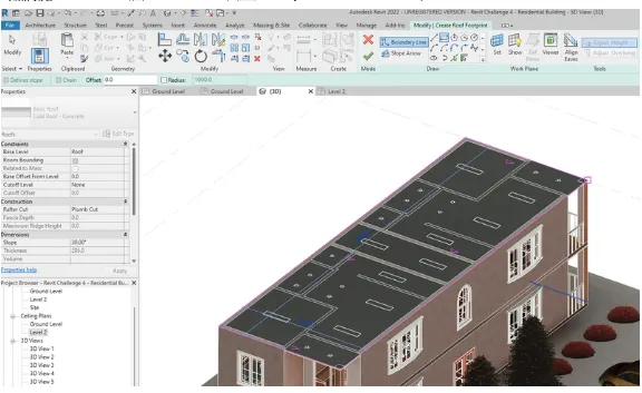
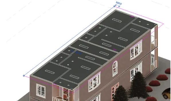
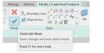
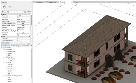
- Once the roof is created, edit its instances inside the properties tab to assign the appropriate values
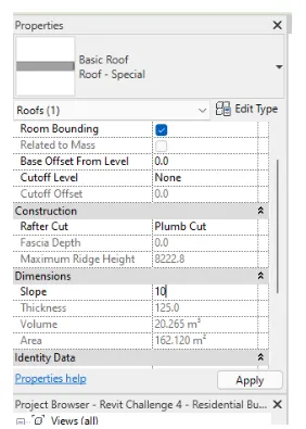
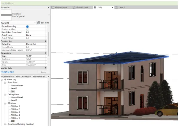
3) Using the file saved from weeks 2 to 4, create plan views for ground floor level and first-floor level including all the walls, floors, and components. Separate them to
architecture and structural plans
Ans:
PROCEDURE:
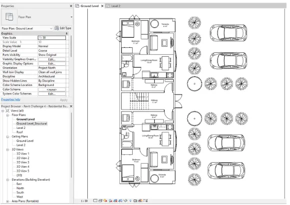
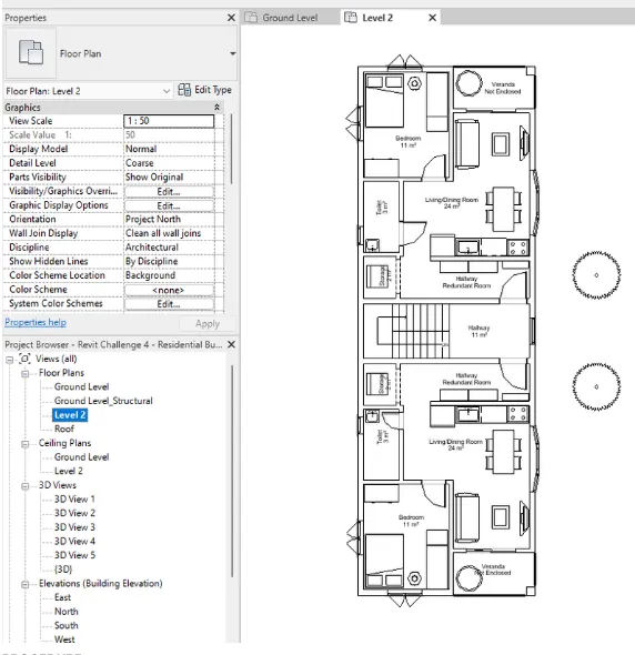
a. Architecture plan must have walls, floors, and all the components placed within the building
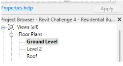
- To create plan views, go to view tab and select the plan views, selectfloor plan for Architectural plans
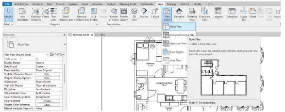
- By default, the first floor plan is already created under the properties tab
---->Ground Floor Level Architectural Plan
---->Level 2 Architactural Plan
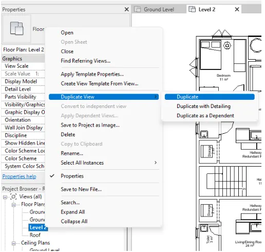
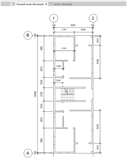
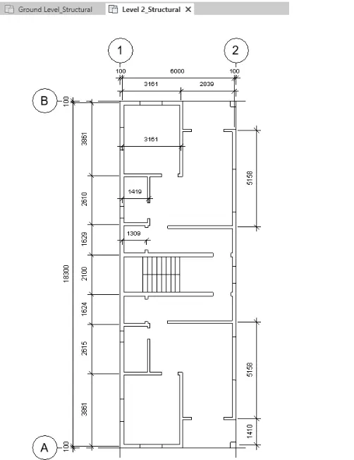
b. Structure plan must have details of only walls, floors, and columns
- Duplicate the Architectural views and rename as XXX_Structural
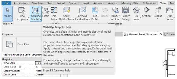
- Go to view the n Visiability/Graphics to control the elements shown in the view
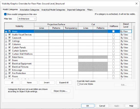
- Uncheck the unnecessary elements for structural view
--->Ground floor level strutural plan
----->Level 2 Structural Plan
4) Using annotate toolbar add dimensions to all the walls and floors with reference to the longitudinal and transverse grids created in the project file
Ans:
PROCEDURE:
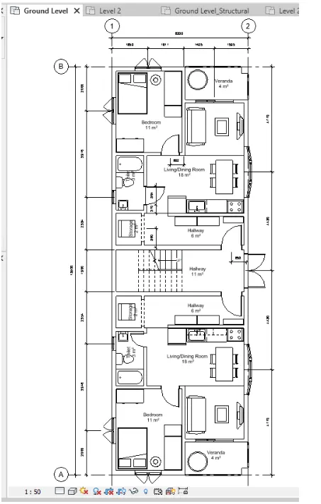
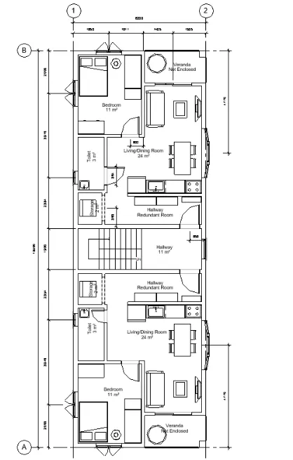
a. The architecture plan dimensions include details on where the components are placed within the buildings with relation to grids. Overall dimensions are sufficient for architecture plans
---->Ground FLoor Level Architectural Plan
--->LEvel 2 Architectural Plan
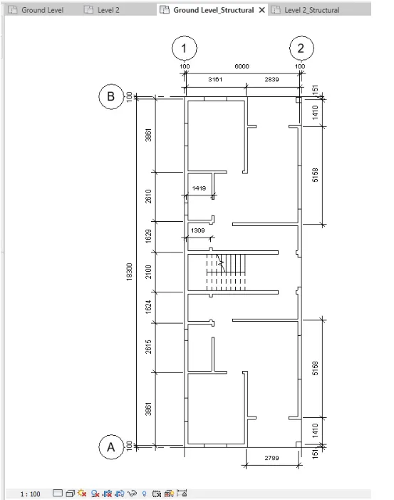
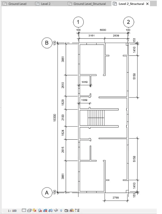
b. The Structure plan dimensions must include details on the position of all the walls and interior walls with reference to grids. Locate all the framing components of the building with reference to a fixed point using Structural plans
--->Ground Floor level Strctural Plan
--->Level 2 Structural Plan
5) Create a sheet template from the view tab and adjust the parameters on the sheet to add appropriate views
Ans:
PROCEDURE:
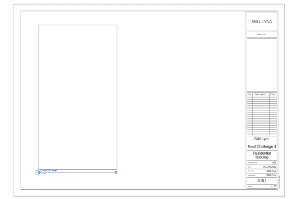
- To add sheets, go to View tab and select sheets
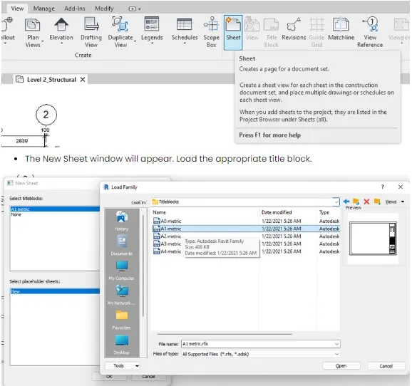
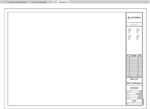
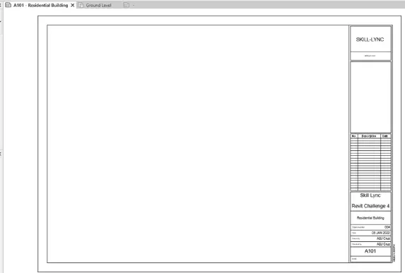
- A sheet will appear. Revise its parameters by licking on the text and changing it ri the approrpiate heaadings. Go to edit family to edit the title block parameters
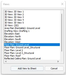
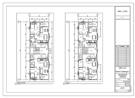
- To add views on the sheet, Go to views tab and select view
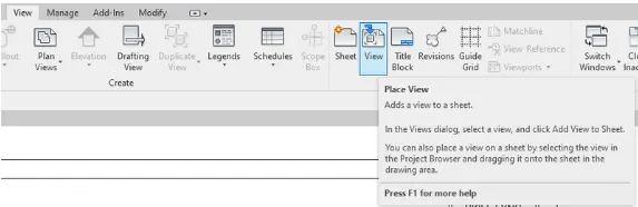
- Select the desired views to insert
6) Using the elevation tab create the elevation views, looking at your building from East, North, South, and West
Ans:
PROCEDURE:
- To show thee elevation views, go to properties tab, Elevatations, and select desired view on the left side of the interface
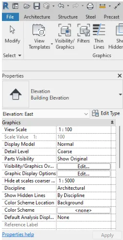
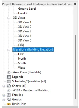
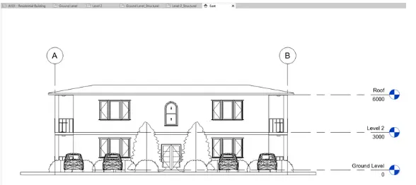
- once the views is opened, edit as desired Add dimension on hide views to showcase desired elevation. you can also duplicate views to create backup views when changing
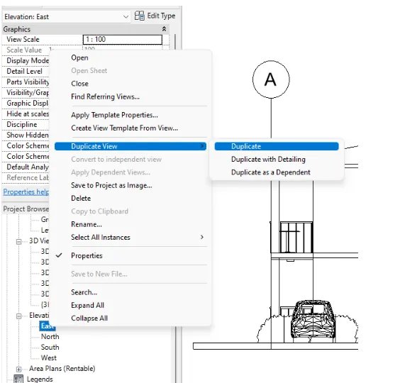
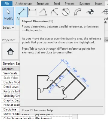
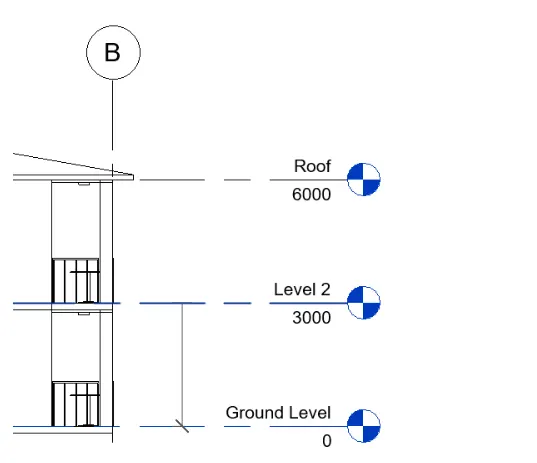
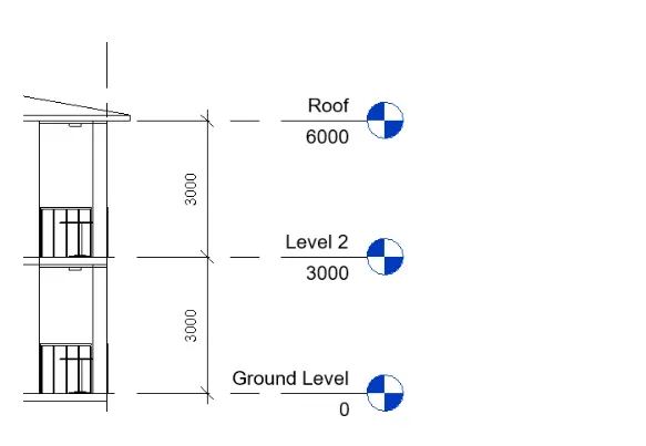
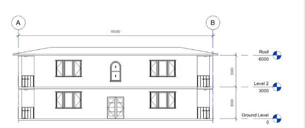
- Add the other required dimension for the views
- Do the same procedure for the other elevations
-----> East Elevation View
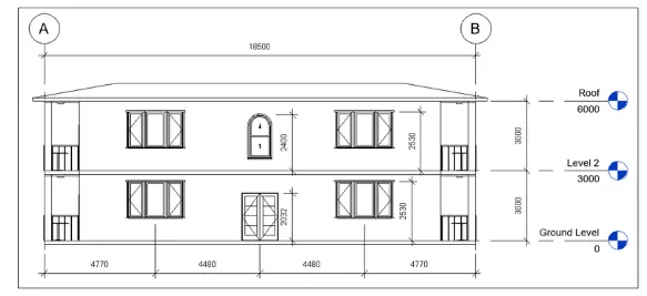
----> North Elevation view
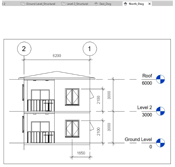
---->South Elevation View
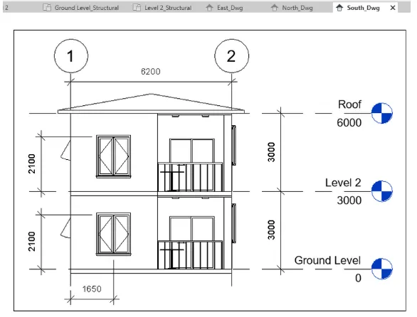
----> West Elevation View
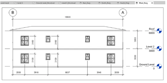
- These views will be added to a different sheet later
7) Produce section cut through each room either cutting across longitudinally or in a transverse direction
Ans:
PROCEDURE:
- To add selections, go to the View you wish to add section to. then under view tab, select the section tool
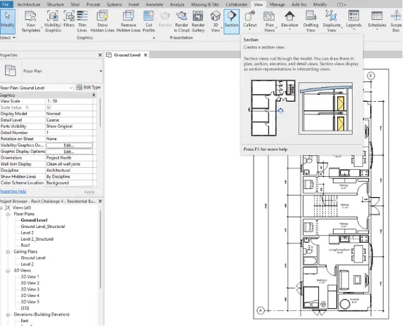
- Add a section to show the bedroom and the living room
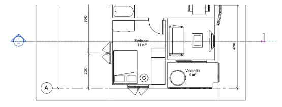
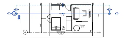
- You can adjust the section scope by dragging the dotted line
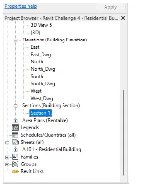
- The section views are under Properties Browser then Sections
- Do the same for the other locations. The sections will be as follows
----->Section 1- Bedroom and living room
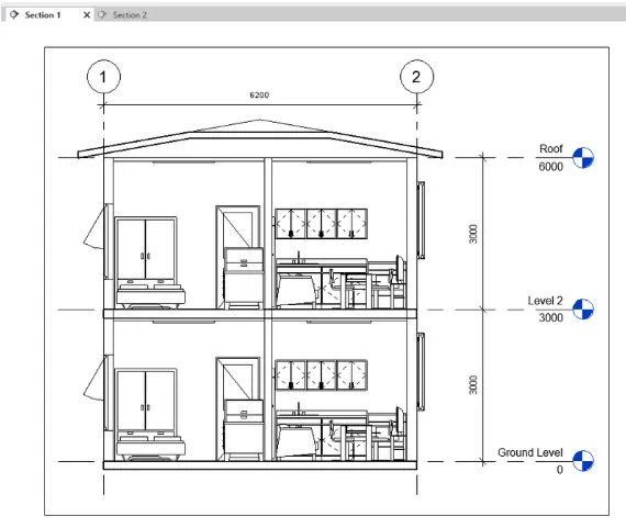
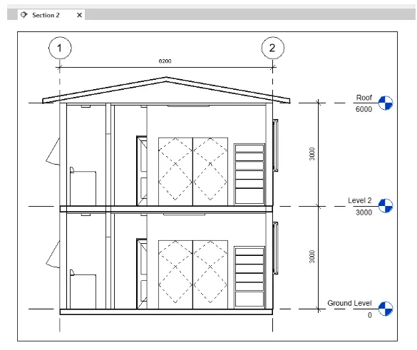
---->Section 2-Storage and Hallway
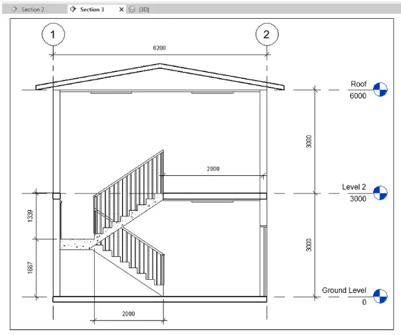
---->Section 3-stair
8) Classify the views, Plan Views, Section Views, and Elevation views to either Design or Documentation category using Properties browser
Ans:
PROCEDURE:
- To Clasify the views, go to view Tab, User interface, then browser Organization
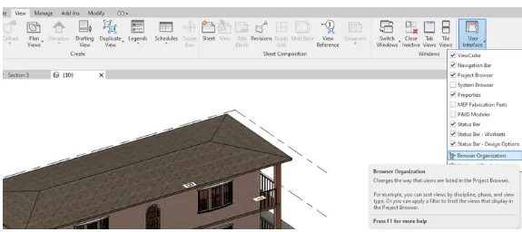
- create a new view xlassification
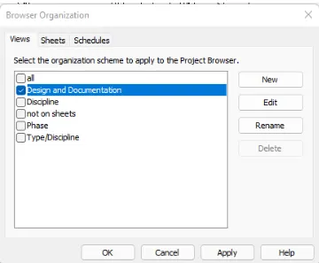
- Now filter/group/sort the views accordingly
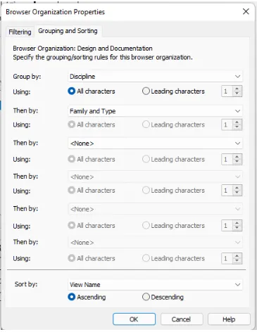
- The views will be sorted as described
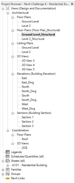
- The design category will hold views related to structural components while the documentation relates to the Architectural Components
9) Using the sheet template produced create multiple sheets as follows
Ans:
General procedure:
- Select sheet tool under view tab
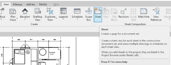
- When the sheet is added.rename accordingly
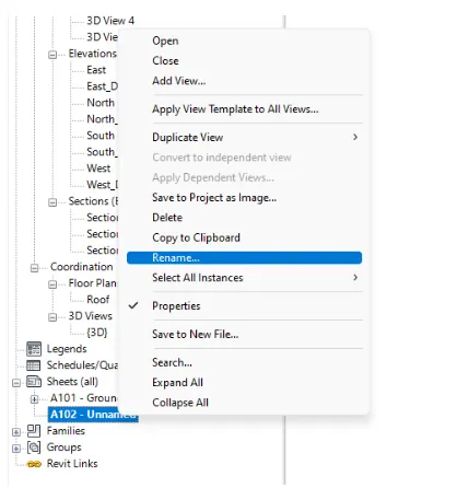
- After renaiming,select the view tool under view tab to start adding views to the sheet
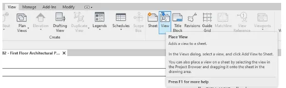
- Once the views sheet is added place it accordingly inside the titleblock
a. A 101- Ground Floor Architecture Plan
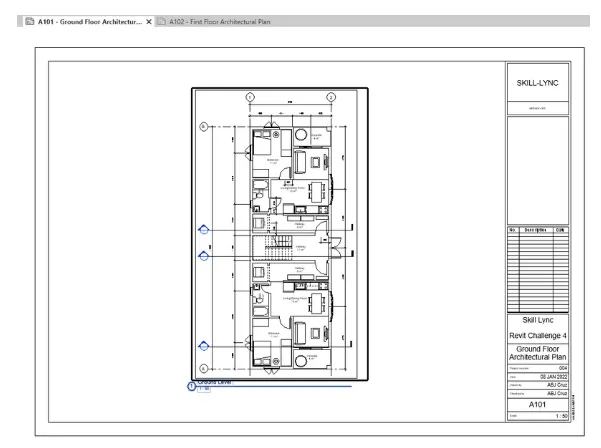
b. A 102- First Floor Architecture Plan
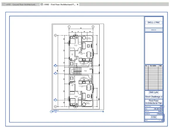
c. A 103- Roof Plan
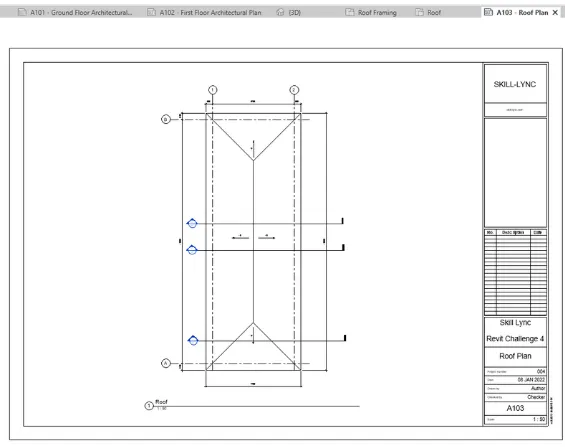
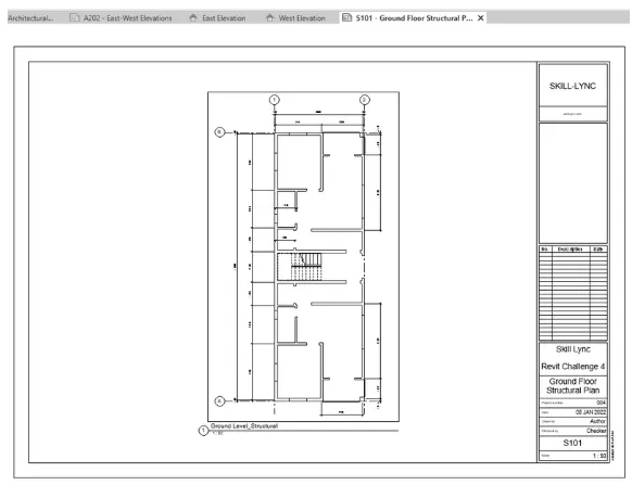
d. S 101- Ground Floor Structural Plan
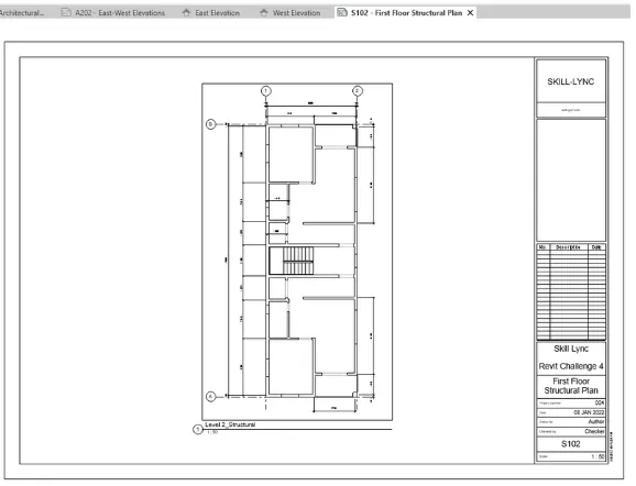
e. S 102- First Floor Structural Plan
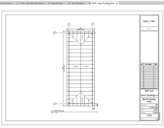
f. S 103- Roof Framing Plan
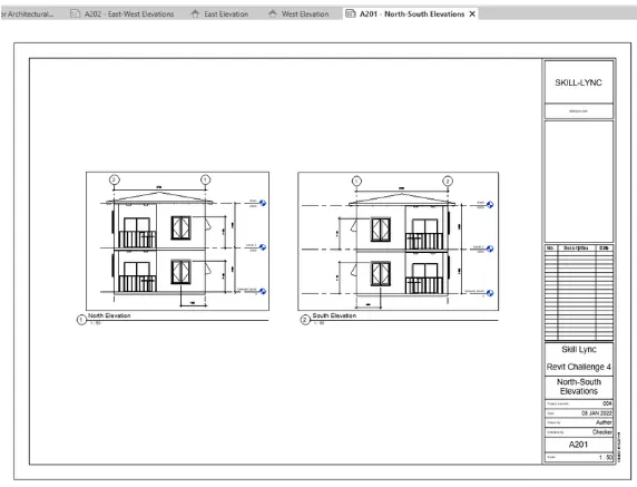
g. A-201- North-South Elevations
h. A-202- East-West Elevations
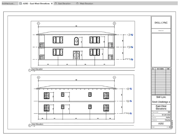
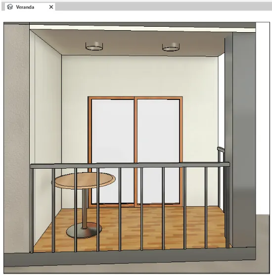
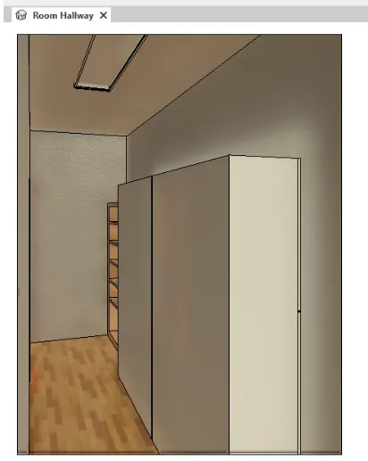
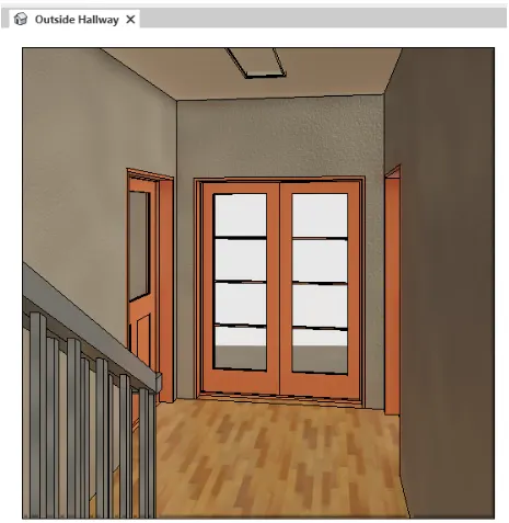
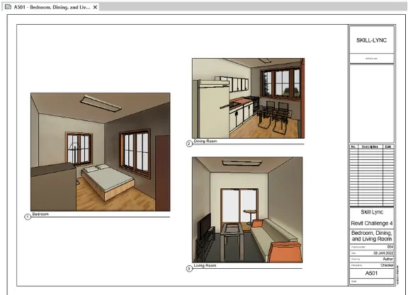
10) Create a camera-specific view or a 3D view in each room ( living, dining, bedroom). Based on the views create a new set of sheets starting A-501 (you can add as many sheets after, 502, 503.. n)to place the 3D view images. Produce the sheets as a part of project drafting.
Ans:
PROCEDURE:
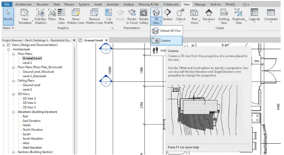
- To add camera views, go to view tab and drag down 3D view. Select the camera tool
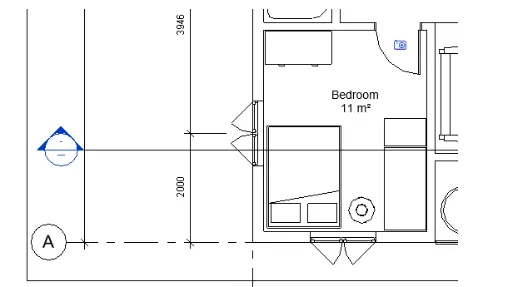
- Apply the camera to your selected location
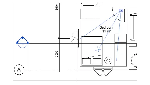
- The view will be shown as below
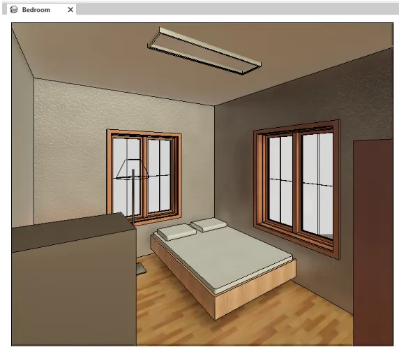
Bedroom
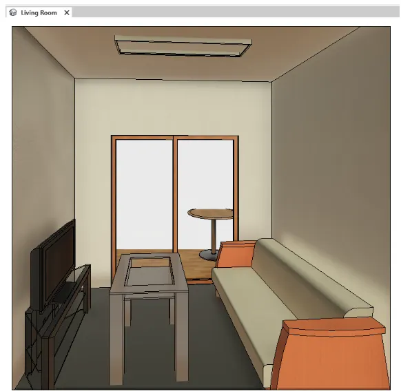
Living room
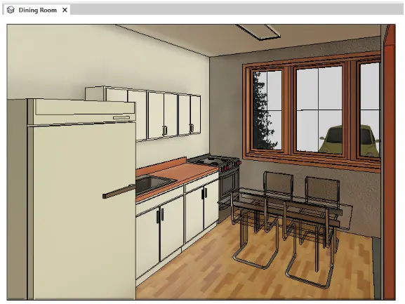
Dining room
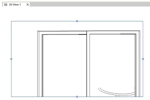
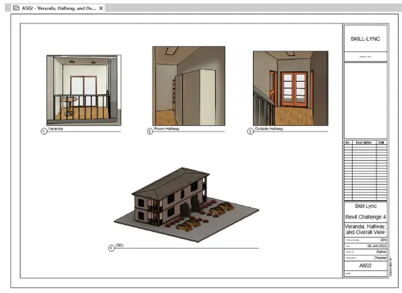
Veranda
Room Hallway
Outside hallway
Apply the created views to sheets the same as in the previous question
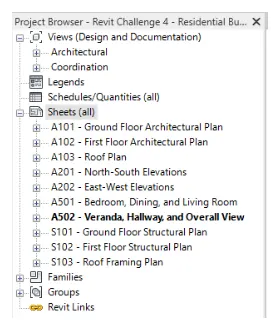
A-501-bedroom, Dining, and Living Room
A-502-Veranda,Hallway, and overall view
The sheets can be seen under the project browser
3.Conclusion
The revit software provides the ability to add or sections that illustartes the created model in 2D layout. These drawings are used for presentation which are given to the client for review.