3D Creation of Celing, Roof, Architectural plan, Structural plan, Sectional view, Elevation view and Camera specific view for a house plan using REVIT
Question :-1
Based on the project saved from Week 3, proceed from the First Floor Level. Model a Ceiling from the architecture tab above the walls at the first-floor level.
Aim :-
- To model a ceiling from architecture tab above the walls at the first floor.
Intoduction :-
- Ceiling, the overhead surface or surfaces covering a room, and the underside of a Floor or a Roof.
- A Part of a building which encloses and is exposed weather in a room, protected shaft or circulation space.
- The creation of the ceiling in the revit is the similar process like Roofs and Floors.
Procedure :-
- Go to Architecture tab.
- Select the ceiling Tool.
- NOw select the Sketching Ceiling tool.
- Choose the pick lines option and select the outer border of external walls.
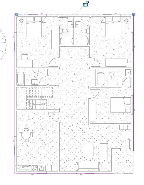
- After selcting the outer border of external walls, Click Ok.
- Ceiling is created in the drawing at the first floor.
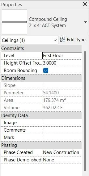
- The properties of the ceiling is as per following.
Result :-
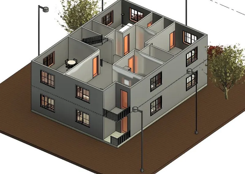
- Celing in the first floor is created from the architecture tab.
Question :-2
Model a roof above the ceiling by selecting the footprints of the ceiling. Using the adjustment toolbars appearing on-screen adjust the roof slope to 10 degrees.
Aim :-
- To Model a roof above the ceiling by selecting the footprints of the ceiling and give the slope of 10 degrees.
Introduction :-
- Revit offers several methods of creating roofs. Choose the method that best meets the needs of your design.
- Roof by footprint is used when you select walls or draw lines in plan view, at level of view in which it was sketched, Slopes are defined when you apply a slope parameter to sketch lines.
Procedure :-
- Go to Architecture tab.
- Select the Roof Tool.
- Choose the pick lines option and select the outer border of external walls.
- Sketch, or pick, a closed loop for the roof.
- Click Ok (Finish Edit Mode), and then open a 3D view.
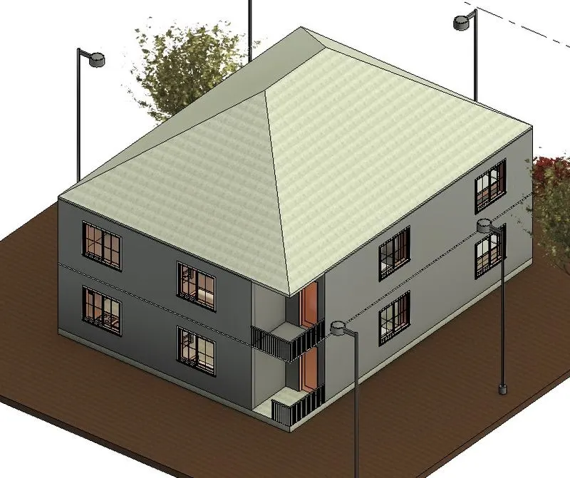
- Roof is creted in the building at the second floor.
- Specify slope defining lines. To change the slope definition of a line, select the line and, on the Properties palette, click Defines Roof Slope. You can then change the slope value.
- When a roof line is set to slope defining appears adjacent to it.
- Change the unit of the slope to degrees.
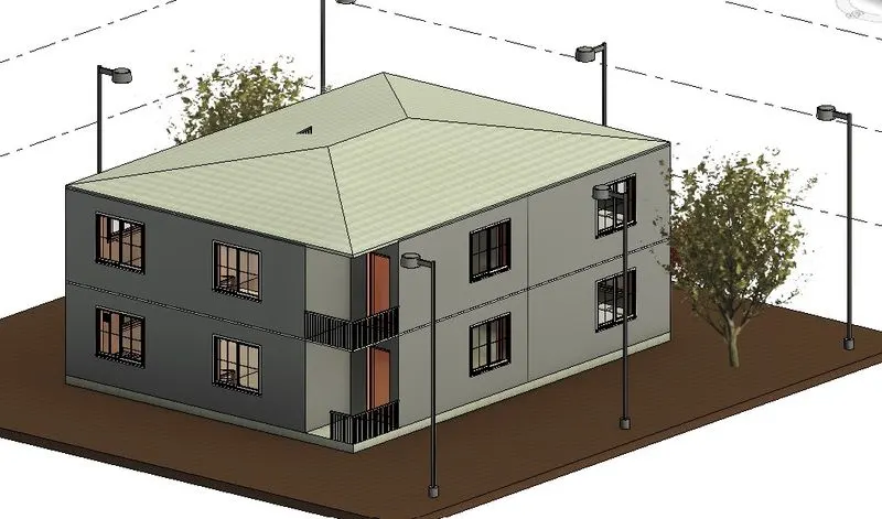
- Insert the slope as 10 degrees.
Result :-
- Roof is created at the second floor and inserted the slope as 10 degrees.
Question :-3
Using the file saved from weeks 2 to 4, create plan views for ground floor level and first-floor level including all the walls, floors, and components. Separate them to architecture and structural plans
a. Architecture plan must have walls, floors, and all the components placed within the building
b. Structure plan must have details of only walls, floors, and columns.
Aim :-
- To create plan views for ground floor level and first-floor level including all the walls, floors, and components and Separate them to architecture and structural plans.
Introduction :-
- Structural plan view is default view when you start new project using structural template.
- Most project include as least one strucural plan.
- New structural plan views are created automatcally as you add the new levels to your project.
- Most project include at least one floor plan.
Procedure :-
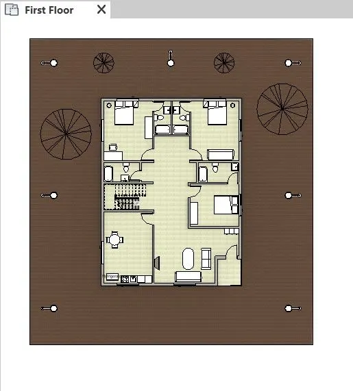
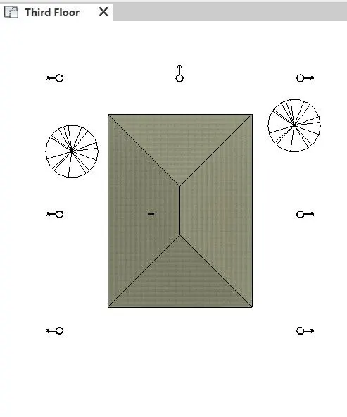
- Architecture Plan views of all the three floors are as per following.
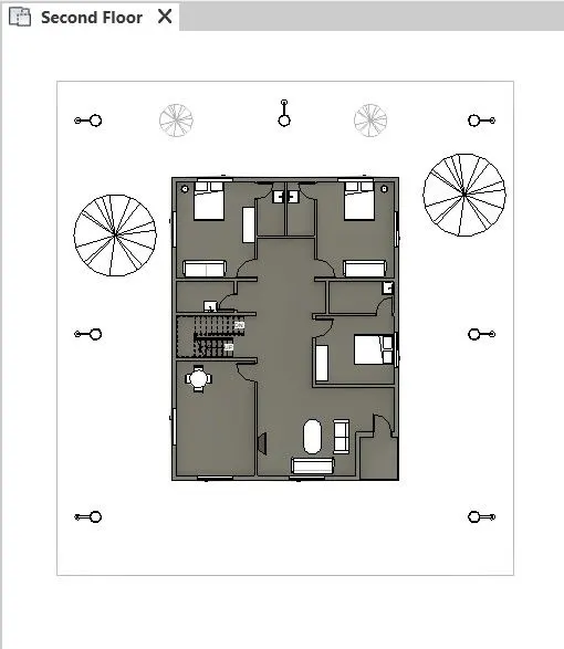
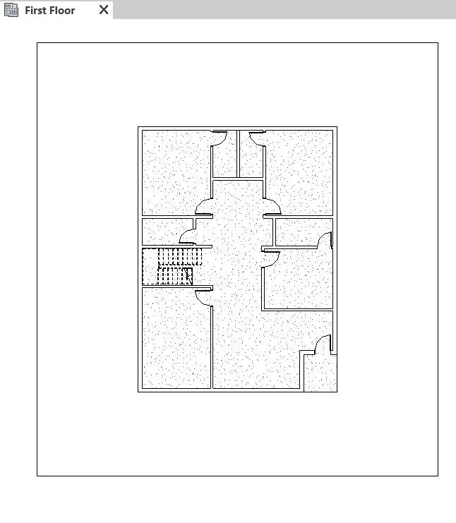
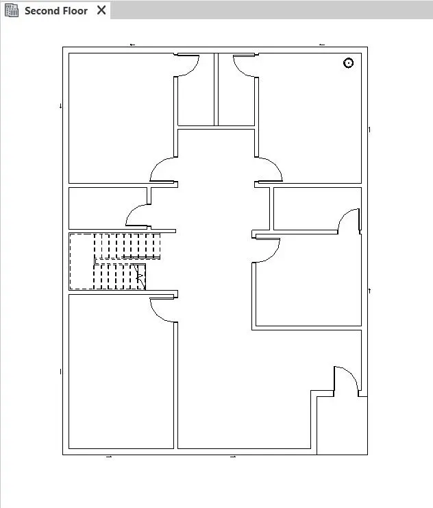
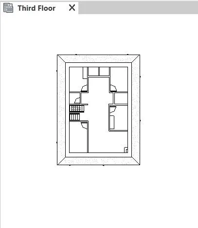
- Structure Plan views of all the three floors are as per following.
Question :-4
Using annotate toolbar add dimensions to all the walls and floors with reference to the longitudinal and transverse grids created in the project file
a. The architecture plan dimensions include details on where the components are placed within the buildings with relation to grids. Overall dimensions are sufficient for architecture plans
b. The Structure plan dimensions must include details on the position of all the walls and interior walls with reference to grids. Locate all the framing components of the building with reference to a fixed point using Structural plans
Aim :-
- To add dimensions to all the walls and floors with reference to the longitudinal and transverse grids created in the project file.
Procedure :-
- We draw the longitudinal and transverse grids to the architectural floor plan as shown below.
- Add the dimension to the architectural plan.
- As the dimensions of the first floor, second floor and the third floor are same, So showing the first floor plan only.
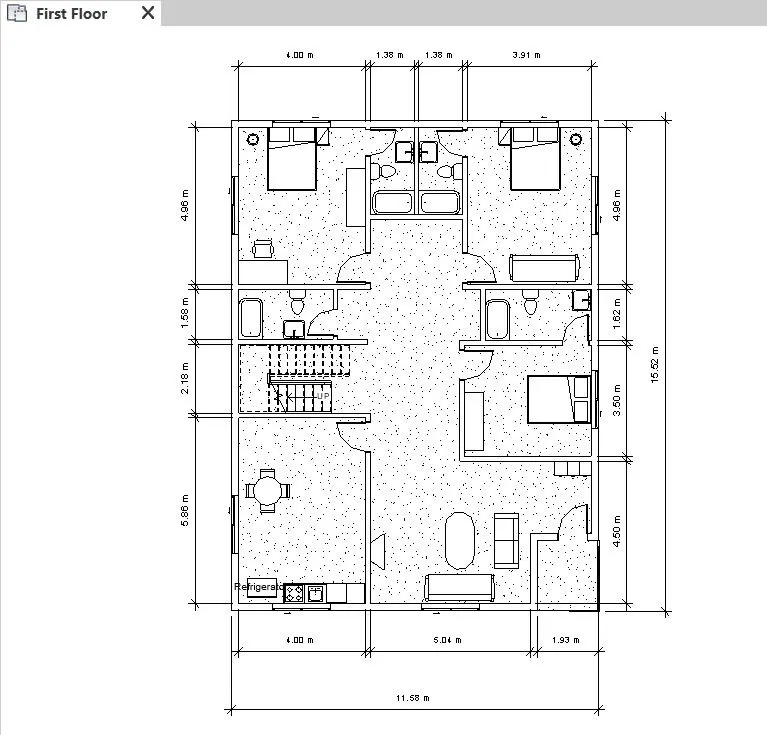
- We draw the longitudinal and transverse grids to the Structural floor plan as shown below.
- Add the dimension to the Structural plan.
- As the dimensions of the first floor, second floor and the third floor are same, So showing the first floor plan only.
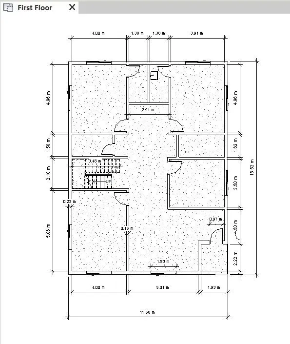
Result :-
- Dimensions are added to all the walls and floors with reference to the longitudinal and transverse grids created in the project file of Architectural an Structural Floor Plan.
Question :-5
Create a sheet template from the view tab and adjust the parameters on the sheet to add appropriate views.
Aim :-
- To Create a sheet template from the view tab and adjust the parameters on the sheet to add appropriate views.
Introduction :-
- In Revit, you create a sheet view for each sheet in the construction document set. You can then place multiple drawings or schedules on each sheet view.
- Create views on a project template before you start building the model to streamline the project documentation process.
- A title block typically displays information about the project, as well as information about individual sheets.
Procedure :-
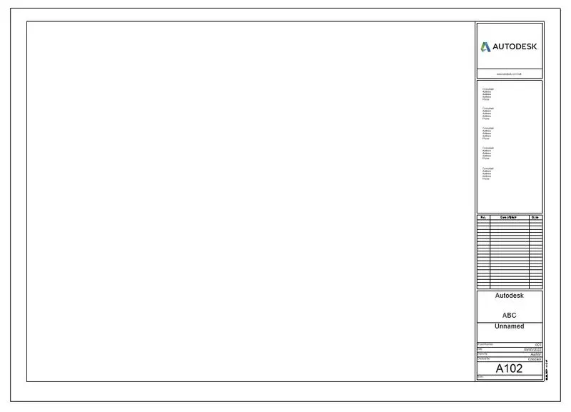
- Click View tab -> Sheet Composition panel -> Sheet
- In the New Sheet dialog, under Select titleblocks, select E1 Metric, and click OK.
- Click the title block to select the sheet, then click the sheet number, enter A1, and press Enter.
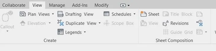
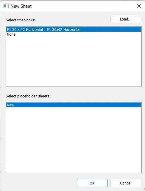
- In the Project Browser, under 3D Views, click theFirst Floor to Building view title and drag it to the upper right corner of the sheet, and release the mouse button.An outline of the view displays for easier placement.
- Click to place the view.
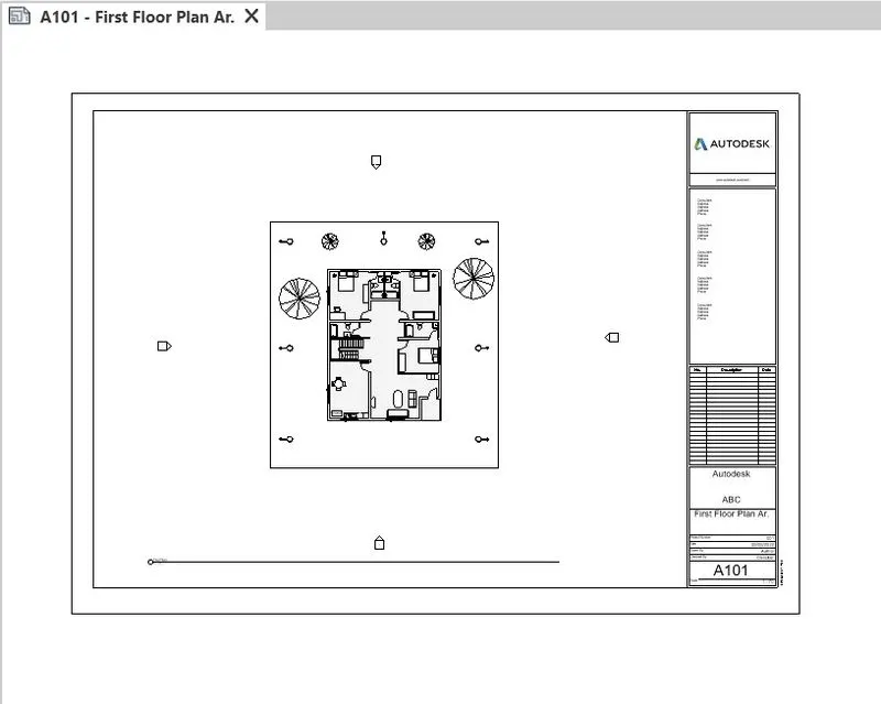
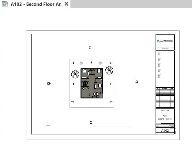
- Using the same method, drag the Second floor plan view below the , moving the view slightly to the right until the centers align, then click to place the view.
- Add the first and second floor plan in the sheets.
Result :-
- Created a sheet template from the view tab and adjust the parameters on the sheet to add appropriate views.
Question :-6
Using the elevation tab create the elevation views, looking at your building from East, North, South, and West.
Aim :-
- To create the elevation views, looking at building from East, North, South, and West.
Procedure :-
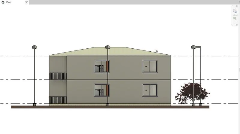
- Click on the elevation tool in view TAb.
- Create the views of all 4 sides.
Result :-
- Created the elevation views, looking at building from East, North, South, and West.
East View
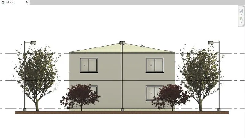
North View
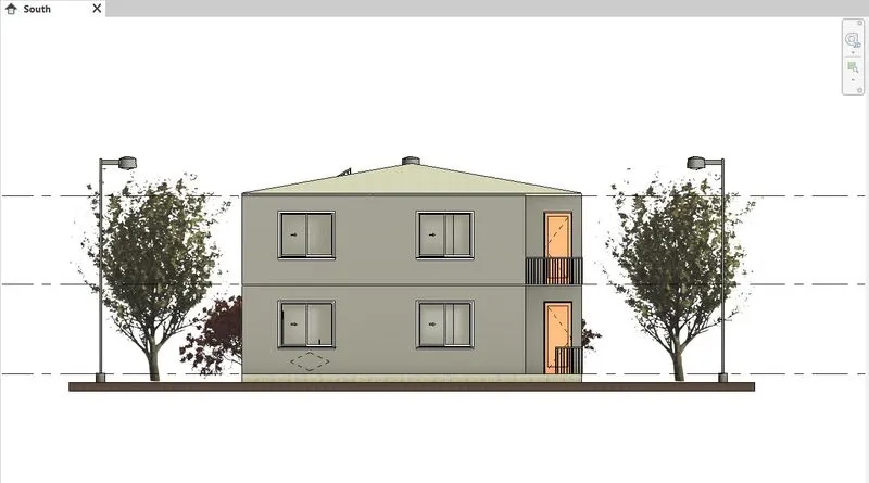
South View
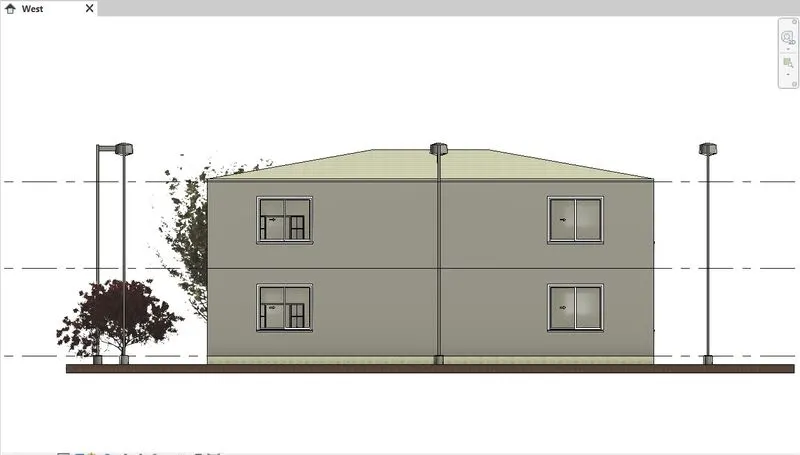
West View
Question :-7
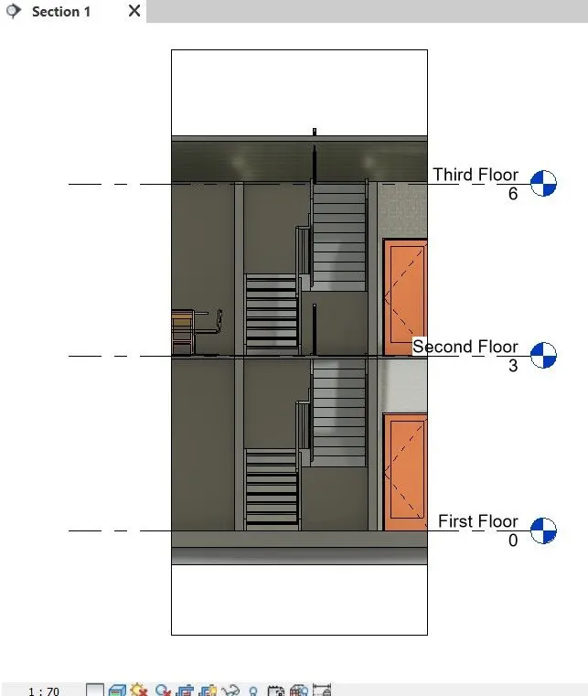
Produce section cut through each room either cutting across longitudinally or in a transverse direction.
Aim :-
- To Produce section cut through each room either cutting across longitudinally or in a transverse direction.
Procedure :-
- Click on the Sections tool in view TAb.
- Create the views of different elements in the building.
Result :-
- Produce section cut through each room either cutting across longitudinally or in a transverse direction.
-
Staircase
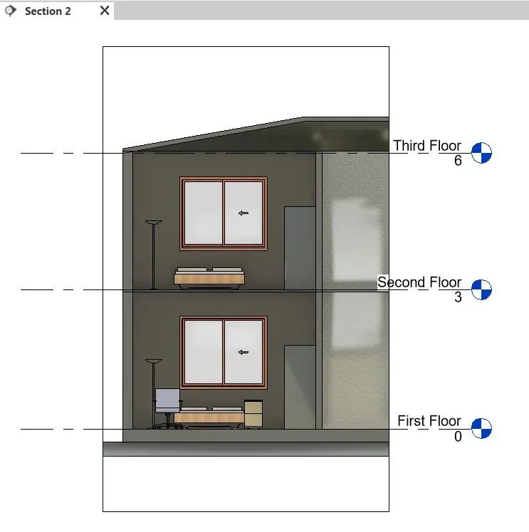
- Bedroom
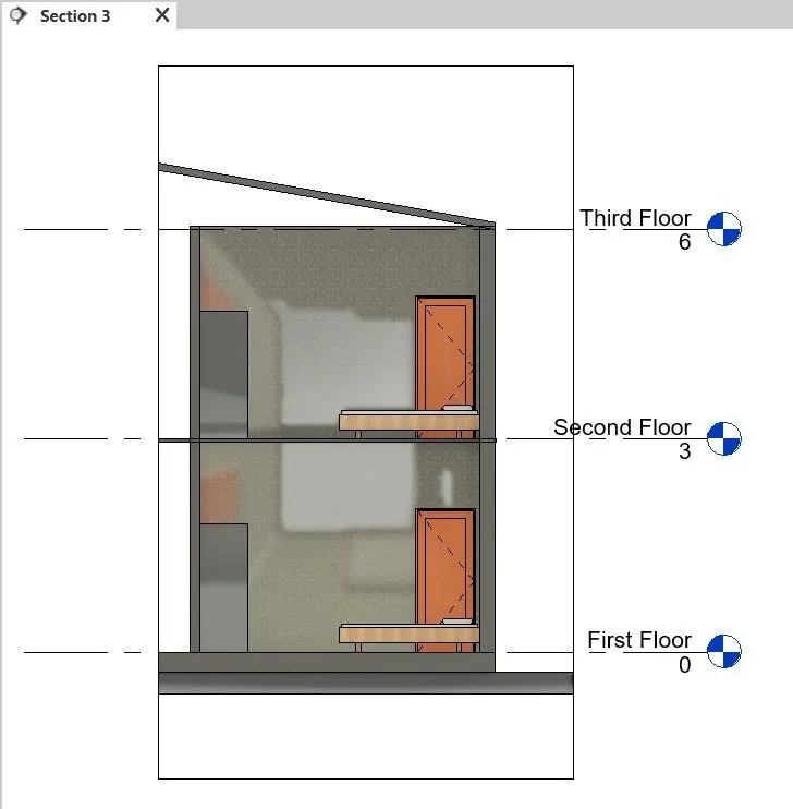
- Bedroom-2
Question :-8
Classify the views, Plan Views, Section Views, and Elevation views to either Design or Documentation category using Properties browser.
Aim :-
- To Classify the views, Plan Views, Section Views, and Elevation views to either Design or Documentation category using Properties browser.
Introduction :-
- In Revit, you create a sheet view for each sheet in the construction document set. You can then place multiple drawings or schedules on each sheet view.
- Create views on a project template before you start building the model to streamline the project documentation process.
- A title block typically displays information about the project, as well as information about individual sheets.
Procedure :-
- Click View tab -> Sheet Composition panel -> Sheet
- In the New Sheet dialog, under Select titleblocks, select E1 Metric, and click OK.
- Click the title block to select the sheet, then click the sheet number, enter A1, and press Enter.
- Add the different views in the sheets and place it.
First Floor Architecture Plan
First Floor Architecture Plan
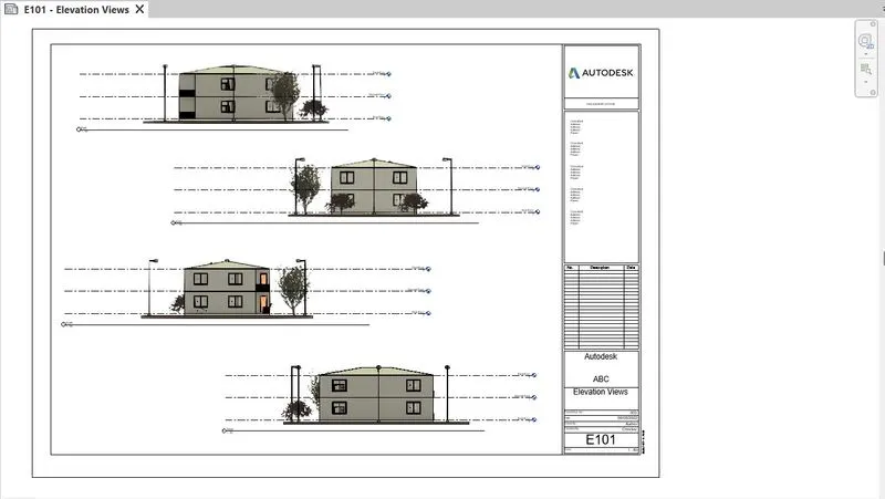
Elevation Views
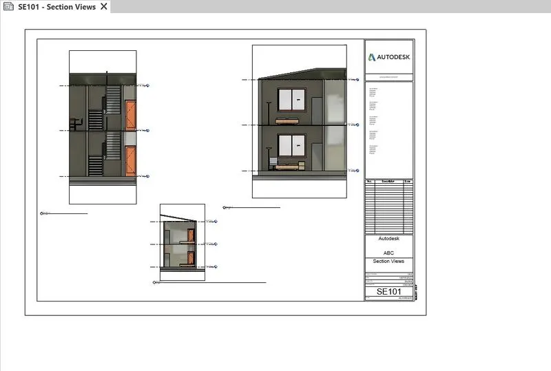
Section Views
Question :-9
Using the sheet template produced create multiple sheets as follows
a. A 101- Ground Floor Architecture Plan
b. A 102- First Floor Architecture Plan
c. A 103- Roof Plan
d. S 101- Ground Floor Structural Plan
e. S 102- First Floor Structural Plan
f. S 103- Roof Framing Plan
g. A-201- North-South Elevations
h. A-202- East-West Elevations
Add additional sheets based on the sections created in your Revit file.
Aim :-
- To produce and create multiple sheets of differetnt views.
Procedure :-
- We have created different sheets that includes the different plans and views.
- Sheets are as per following.
Result :-
- Created multiple sheets of differetnt views.
A-101 Ground Floor Architecture Plan
A-102 Ground Floor Architecture Plan
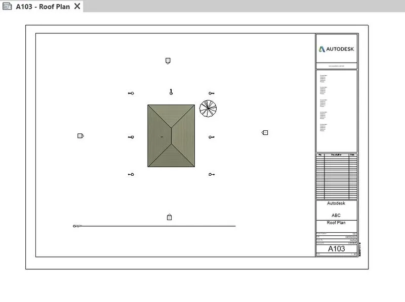
A-103 Roof Plan
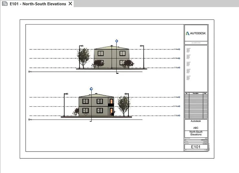
E-101 North-South Elevations
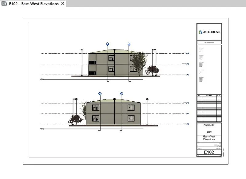
E-102 East-West Elevations
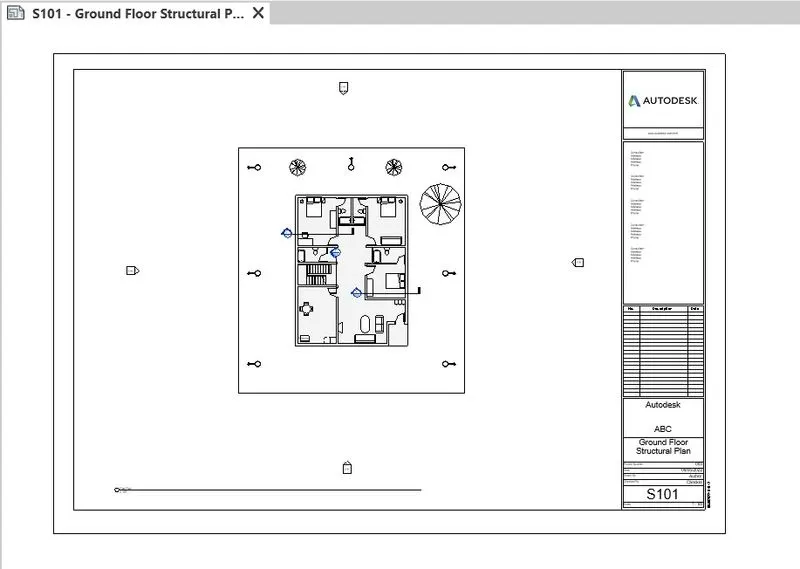
S-101 Ground Floor Structure Plan
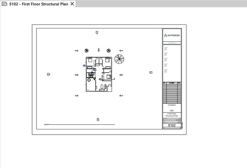
S-102 First Floor Structure Plan
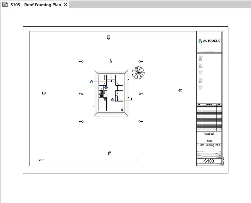
S-103 Roof Framing Plan
SE-101 Section Views
Question :-10
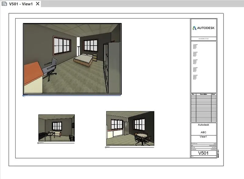
Create a camera-specific view or a 3D view in each room ( living, dining, bedroom). Based on the views create a new set of sheets starting A-501 (you can add as many sheets after, 502, 503.. n)to place the 3D view images. Produce the sheets as a part of project drafting.
Aim :-
- To Create a camera-specific view or a 3D view in each room and Based on the views create a new set of sheets.
Procedure :-
- Click on the View tab, Create panel, 3D View drop-down triangle, and click Camera.
- Save the different views.
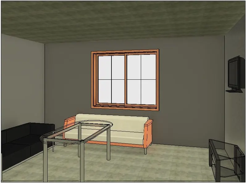
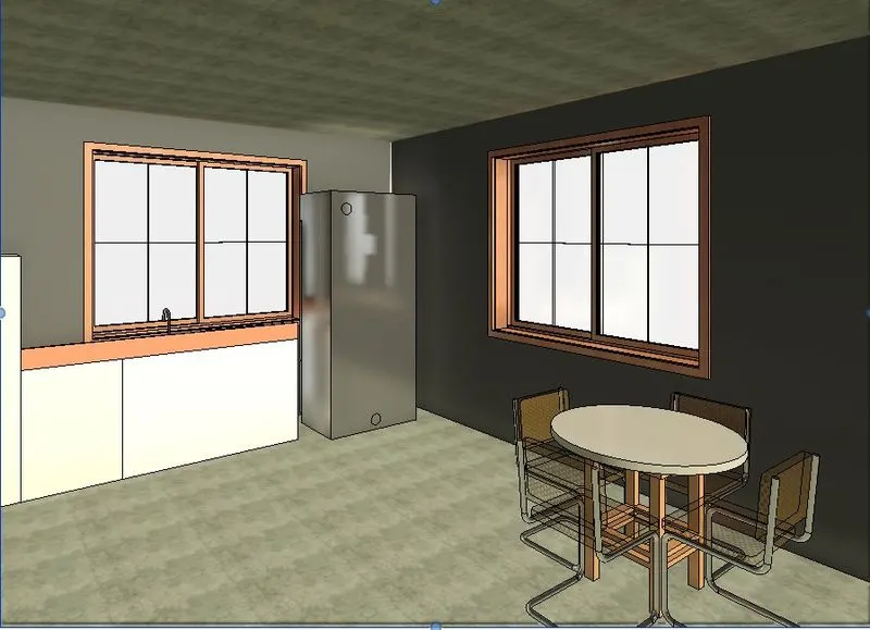
- Take a sheet and name it as V-501.
- Go to the Views and drop on the sheet.
- Set the different views in the sheets.
Result :-
- Sheet is created that includes th camera-specific views named as V-501.