2D Meshing of Sheet Metal Model - 1
AIM :
To generate 2D meshing for the given sheet metal model.
OBJECTIVES :
1. For the given sheet metal model, check and resolve all the geometrical errors.
2. Create a mid-surface for all the components.
3. Generate 2D meshing for the mid-surface such that it clears all the provided quality criteria and the features in the model are captured properly with a good mesh flow.
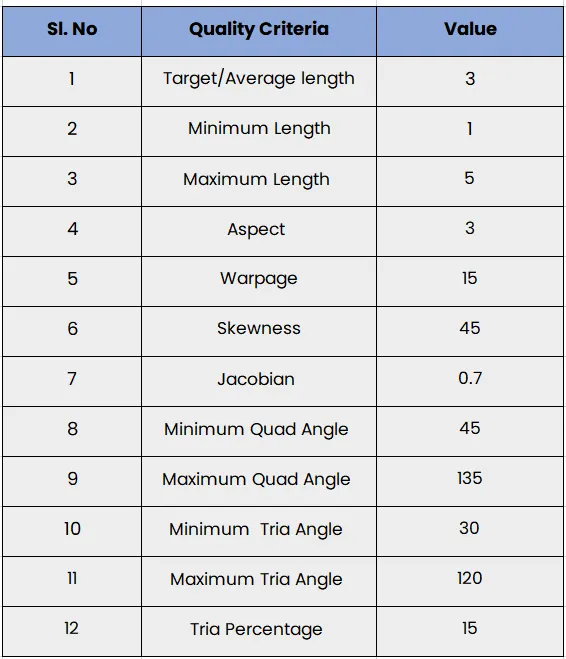
QUALITY CRITERIA :
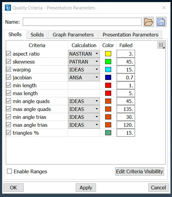
The reference quality criteria values are given as follows.
PROCEDURE :
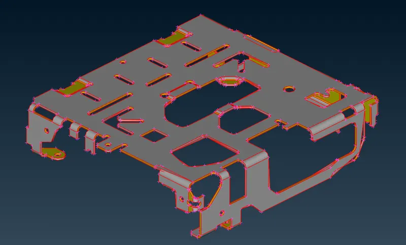
The first and foremost step in the procedure is importing the sheet metal component which is in the ‘iges’ file format, into the ANSA software. The imported geometry is as shown below.
Geometry Cleanup :
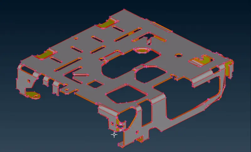
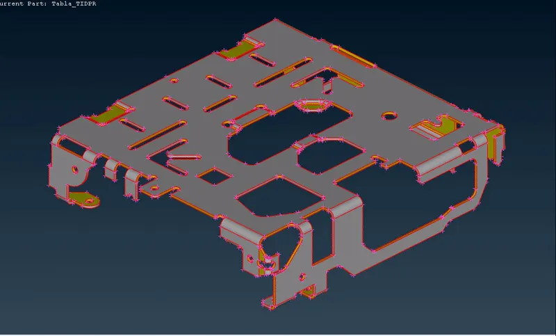
The first step in performing geometry cleanup is increasing the CONS resolution such that all the features of the geometry are properly captured.
Before Increasing CONS Resolution :
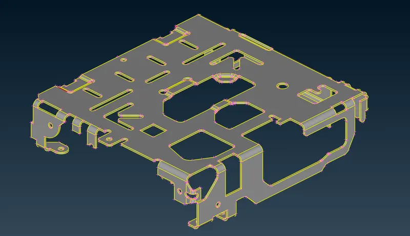
After Increasing CONS Resolution :
Further, we use the ‘topo’ function to achieve connectivity between the CONS throughout the component. Also, we orient the entire geometry such that all the surfaces are towards a single normal direction (grey on the outside, yellow on the inside).
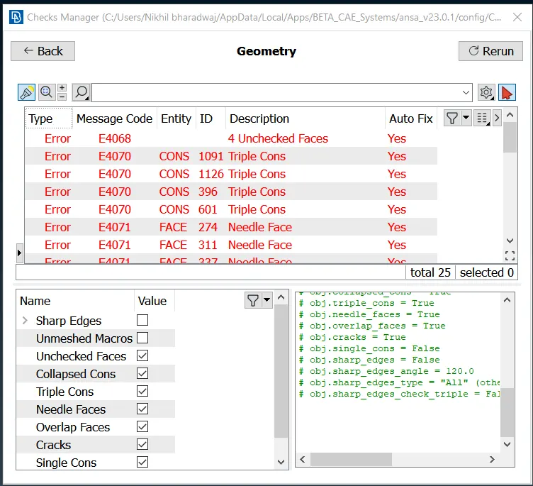
Next, we run a geometry check to identify the various errors present in the parent geometry. These errors are further resolved one by one such that the geometry is free of errors.
Mid Surface Creation :
After resolving the geometrical errors of the component, we then move further to create a mid-surface for the same. Here, we use the ‘skin’ method to extract the mid-surface. The respective faces of the component which we are going to offset is selected as follows.
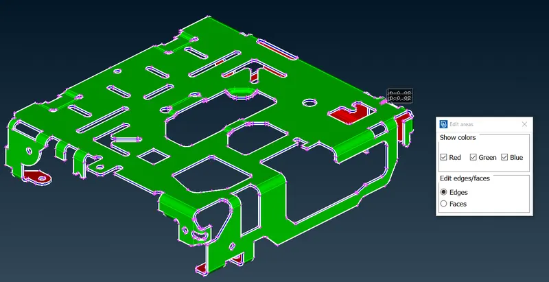
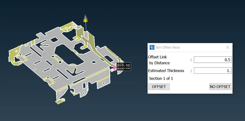
Further, we select the side (red surface) of the component which we are going to offset. We provide an offset distance value of 0.5 such that the mid surface is created at exactly half the thickness of the parent geometry.
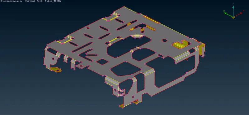
Finally, we hide the parent geometry to obtain the extracted mid surface as shown.
Meshing :
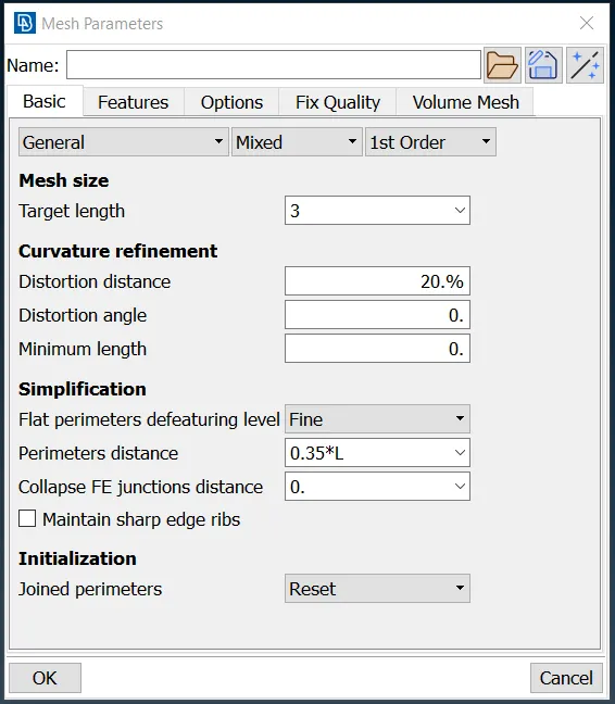
After the mid-surface has been successfully extracted, we then move on to meshing. Before meshing, we first define the target length of the required mesh to be generated (i.e., 3 mm), under the mesh parameters tab.
The quality criteria parameters are defined as per the problem statement, such that a good mesh quality is achieved.
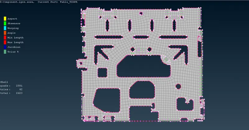
With reference to the above defined quality criteria, we then generate mixed (quad & tria) meshing for each part of the mid surface.
- The fillets and curvatures of the model are meshed such that there are no resulting skewed or off elements.
- A smooth mesh flow around the areas of holes are obtained by using the ‘slide’ function to rotate the hole geometries such that its faces are parallel to the nearest perimeter.
- We use the ‘split’ function to resolve the triangles formed in the mesh. The triangles are resolved as much as possible such that there aren’t any adjoining trias or trias near the perimeters of the model.
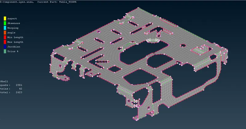
- All the off elements are cleared and thereby obtaining a smooth mesh flow, of which all the elements clear the quality criteria.
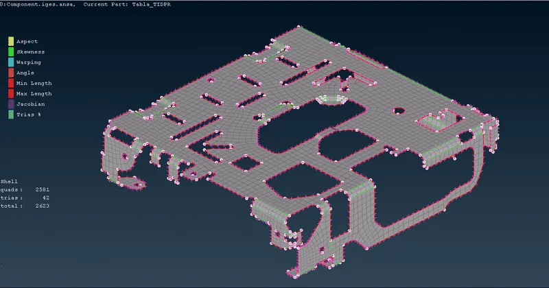
The final meshed model of the mid-surface is obtained as shown.
360o360� View of Meshed Model :
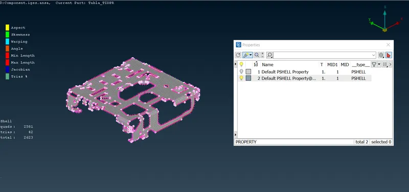
Finally, we assign the thickness of 1mm to the mid-surface in the PID tab. We thereby obtain our final geometry.
LEARNING OUTCOMES :
- Basics of sheet metal modelling in ANSA.
- Increasing the resolution of CONS to capture the features in higher detail.
- Identifying geometrical errors and resolving them by performing geometry cleanup.
- Extraction of mid-surface from the given component using the skin / offset options.
- Defining quality criteria to obtain a smooth mesh flow and fixing the off elements if any.
- Generating 2D meshing for the mid-surface and resolving triangles by using various GUI commands.
- Best practices to follow to obtain smooth mesh flow.
- Assigning thickness to the mid-surface, as a PID property.
CONCLUSIONS :
For the given sheet metal component, geometry cleanup has been carried out and a mid-surface has successfully been extracted. 2D meshing has been generated for the mid-surface, thereby clearing all the provided quality criteria (no off elements). The number of trias in the meshing are minimized as much as possible, thereby obtaining a smooth mesh flow.
During the meshing process, it can be observed that manual meshing of each individual section of the components leads to more accurate results. Also, dividing the mesh regions in the form of near squares results in better and smoother mesh flow across the component.
Final ANSA Model : https://drive.google.com/file/d/1Yw38iwMTw5o9nSArPqRbzm25aNTZp5db/view?usp=share_link