Airfoil terminology: parts of an airfoil, diagram and how it works
An airfoil (aerofoil) is the cross-section shape of a wing, propeller blade or turbine blade, shaped to make lift from the air flowing past it. Here a NACA 2412 section, the wing-root airfoil of the Cessna 172, is built and rendered in 3D with every term labelled, then put in a computed airflow at 0°, 5° and 10° so you can see where the lift comes from.
By Skill-Lync · Published 22 Nov 2026 · Teaching model built and rendered in Blender from code · Flow computed with a panel method
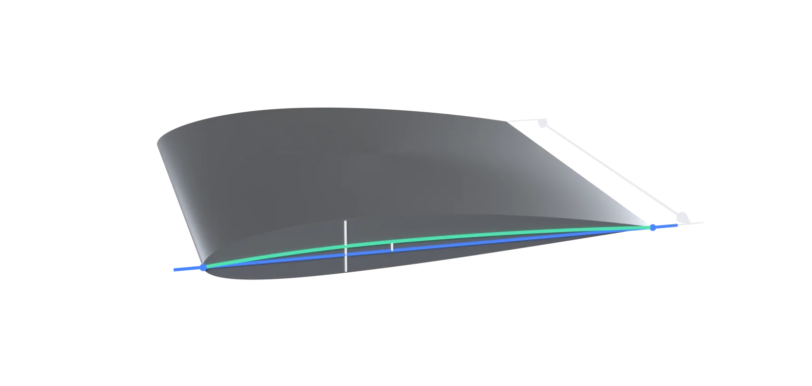
- 1Upper surface
- 2Leading edge
- 3Maximum thickness
- 4Maximum camber
- 5Trailing edge
- 6Span (segment)
- 7Mean camber line
- 8Chord line
- 9Lower surface
What is an airfoil?
An airfoil is the shape of a wing seen in cross-section: rounded at the front, thin at the back, usually more curved on top than underneath. The FAA defines it as "a structure designed to obtain reaction upon its surface from the air through which it moves". Wings, tailplanes, propeller and helicopter blades, compressor and turbine blades, wind turbine blades and racing car wings all use airfoil sections.
Think of the airfoil as the wing's DNA. A wing is many airfoil sections stacked along its span, sometimes changing in size and shape from root to tip. Get the section right and the wing lifts efficiently and stalls gently; get it wrong and no amount of wing area fixes it.
Parts of an airfoil and their functions
The parts of an airfoil are the leading edge, trailing edge, upper surface and lower surface. Its shape is described by the chord line and chord, the mean camber line, the maximum camber and maximum thickness (each with its position along the chord) and the leading-edge radius. Angle of attack, relative wind, centre of pressure and aerodynamic centre describe it in flight.
| Term | What it is and why it matters |
|---|---|
| Leading edge | The front point of the section, where the air first meets it. The FAA describes it as "the rounded end, which faces forward in flight". A round leading edge lets the airfoil work over a range of angles of attack without the flow breaking away at the nose. |
| Trailing edge | The rear point, "quite narrow and tapered" (FAA). Air from the upper and lower surfaces leaves it smoothly (the Kutta condition), which is what fixes how much lift the section makes. |
| Chord line | The straight line joining the leading and trailing edges. Angles (angle of attack, incidence) and positions ("30% of the chord") are measured from it. |
| Chord (c) | The length of the chord line. Every airfoil dimension is quoted as a fraction of it, so one shape works at any size. |
| Mean camber line | The line halfway between the upper and lower surfaces. NACA Report 824 builds every section by laying the thickness off perpendicular to this line. |
| Camber (maximum camber) | The largest distance between the mean camber line and the chord line, and where along the chord it occurs. NACA 2412: 2% of the chord at 40% chord. More camber means more lift at a given angle, and a stronger nose-down pitching moment. |
| Thickness (maximum thickness) | The largest distance between the upper and lower surfaces, as a percentage of the chord: 12% at 30% chord for NACA 2412. Thickness gives room for spars and fuel and affects drag and how gently the section stalls. |
| Upper surface | The top of the section, more curved than the bottom. Air over it speeds up and its pressure falls below atmospheric: the FAA notes this suction "creates a relatively larger force on the wing" than the pressure underneath. |
| Lower surface | The bottom of the section, "usually somewhat flat" (FAA). When the airfoil lifts, the pressure here is higher than on the upper surface. |
| Leading-edge radius | The radius of the circle that fits the nose. For NACA 4-digit sections it is 1.1019 t², about 1.6% of the chord for a 12% thick section. Report 460 warns that a small radius strongly cuts the maximum lift. |
| Angle of attack (α) | The angle between the chord line and the relative wind. Lift grows with it until the critical angle, where the flow separates and the airfoil stalls. |
| Relative wind | The direction of the air relative to the airfoil, opposite to the direction it moves. Lift is defined perpendicular to it and drag parallel to it. |
| Centre of pressure | The point on the chord where the total aerodynamic force acts. It moves forward as the angle of attack rises (FAA): from 46% to 30% of the chord between 0° and 10° on this section. |
| Aerodynamic centre | The point about which the pitching moment does not change with angle of attack. Thin-airfoil theory puts it at the quarter chord, which is why moments are quoted about c/4. NACA's tests (Report 824) found it slightly ahead of c/4 for the 24-series, NACA 2412 included. |
Airfoil terminology diagram (NACA 2412, to scale)
The section below is drawn from the NACA equations, true to scale. Its thickness is 12% of the chord at 30% chord, its camber 2% at 40% chord, and its leading-edge radius 1.6% of the chord.
Angle of attack, relative wind, lift and drag
The FAA defines the angle of attack as "the acute angle between the chord line of the airfoil and the direction of the relative wind". Lift acts perpendicular to the relative wind and drag parallel to it, both through the centre of pressure.
How does an airfoil work?
An airfoil works by turning the air that flows past it. Its camber and angle of attack bend the flow downward; by Newton's third law the air pushes the airfoil up. The same turning makes the air speed up over the upper surface, where its pressure falls well below atmospheric, while the pressure under the lower surface stays higher than on top. (At 0° both surfaces are slightly below atmospheric over the front half; at 5° and 10° the lower surface is above it.) The pressure difference across the section, added up over the whole surface, is the lift.
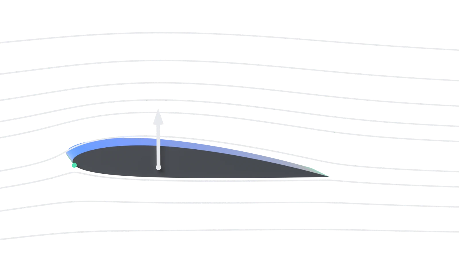
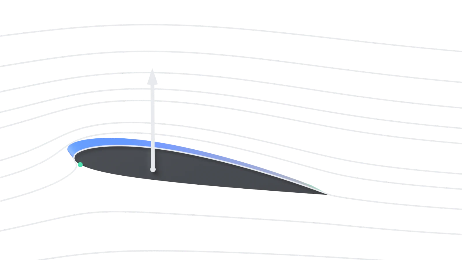
The frames below are not drawings. The flow is computed with a panel method (Hess-Smith sources plus a vortex, with the Kutta condition at the trailing edge, 240 panels), checked against the site's independent vortex panel method to about 0.5%. The surface colour is the pressure coefficient: blue where the pressure is below atmospheric, mint where it is above. The camera looks from slightly above, so only the upper surface's colour shows; the lower surface is seen edge-on. For the full derivation of lift with a worked aircraft example, see how does an airfoil work.
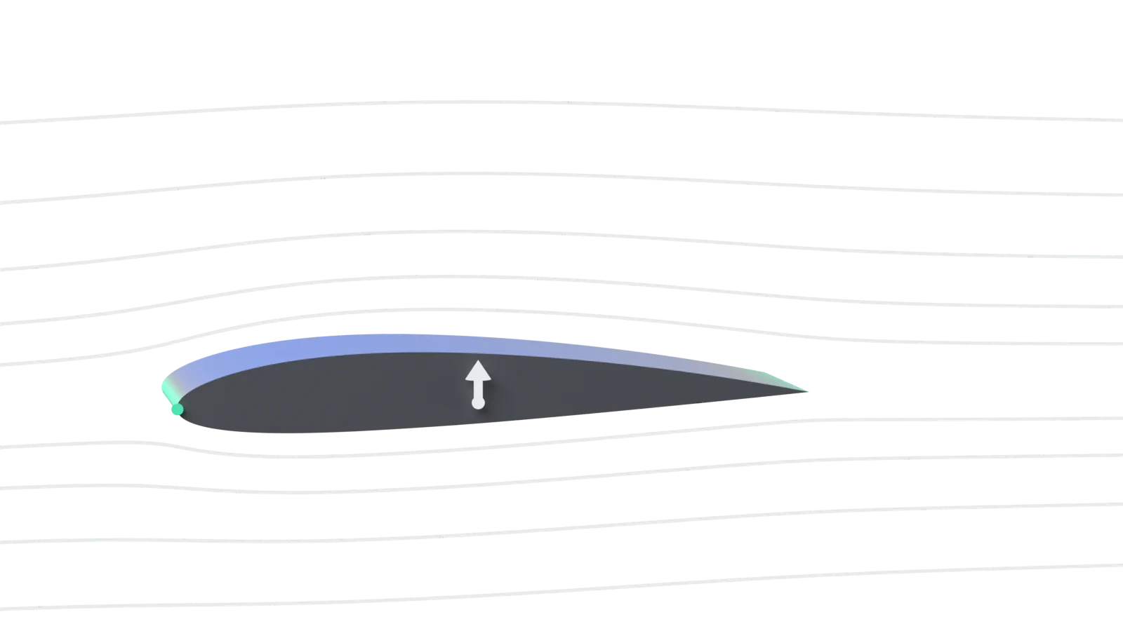
- 1Relative wind
- 2Low pressure (suction)
- 3Stagnation point
- 4Higher pressure
- 5Lift
- 6Centre of pressure
0°: camber alone makes lift. At zero angle of attack the chord line points straight into the relative wind, yet the cambered NACA 2412 still lifts: the panel method gives a lift coefficient of 0.26. The flow speeds up over the curved upper surface (blue, below atmospheric pressure), the stagnation point (mint) sits right at the nose, and the centre of pressure is far back, at 46% of the chord.
5°: the cruise-climb range. Tilt the section up 5° and the stagnation point moves under the nose, the flow over the top speeds up more and the suction peak climbs to a pressure coefficient of -1.9 just behind the leading edge. Lift rises to 0.86 (inviscid; XFOIL with friction gives 0.81 at a Reynolds number of 1 million). The centre of pressure moves forward to 32% of the chord.
10°: high lift, close to the limit. At 10° the air has to turn sharply around the nose: the suction peak reaches -5.9, and behind it the pressure has to rise all the way back to the trailing edge. That rising pressure is what the real boundary layer eventually cannot climb. Lift is 1.45 here without friction (XFOIL: 1.27). About 6° more (XFOIL's maximum lift is at 16.5°) and the flow separates from the upper surface, the separation spreading forward from the trailing edge: the stall.
Relative wind from the left, horizontal; the section is pitched nose-up about its quarter chord. Lift arrow length (to the tip) is proportional to the lift coefficient. "Higher pressure" points at the edge of the lower surface: pressure there is higher than on the upper surface at the same chord position. Inviscid flow: no boundary layer, so no drag and no stall in these frames.
Airfoil lift with numbers: three methods side by side
Lift per metre of span comes from the dynamic pressure, the chord and the lift coefficient. Thin-airfoil theory predicts the lift coefficient from the camber line alone:
| α | Panel method | Thin-airfoil theory | XFOIL, Re 1 million | Centre of pressure | Lowest Cp |
|---|---|---|---|---|---|
| 0° | 0.26 | 0.23 | 0.24 | 46% | -0.57 |
| 5° | 0.86 | 0.78 | 0.81 | 32% | -1.9 |
| 10° | 1.45 | 1.32 | 1.27 | 30% | -5.9 |
Thin-airfoil theory gives a zero-lift angle of -2.08° for NACA 2412, and NACA's variable-density tunnel measured -1.7° (Report 460, Reynolds number about 3 million). Thickness adds about 10% of lift in inviscid flow; at 0° and 5° the boundary layer takes most of it back, so XFOIL lands between the two, and by 10° it takes back more than thickness adds. Above about 10° the methods split: XFOIL's lift curve bends over to a maximum of 1.58 at 16.5°, while the inviscid methods keep rising, with no stall. Report 460 measured a maximum of 1.59 on a rectangular wing of aspect ratio 6 (a 3D model, not a 2D section).
Worked example: a light aircraft wing section with a 1.5 m chord (assumed) at 50 m/s at sea level (ρ = 1.225 kg/m³) and 5° angle of attack, using XFOIL's cl of 0.81: . The Reynolds number there is about 5.1 million, higher than XFOIL's 1 million, so the real value would be a little higher.
What happens when an airfoil stalls?
An airfoil stalls when the angle of attack passes its critical angle: the airflow separates from the upper surface and lift drops quickly. The FAA puts the critical angle at approximately 16° to 20° depending on the aircraft's design, and stresses that a given aircraft always stalls at the same angle of attack regardless of airspeed, weight, load factor or density altitude.
The 10° frame shows why. The suction peak just behind the nose is very strong, so the pressure has to rise a long way from there to the trailing edge. The slow air in the boundary layer runs out of energy climbing that pressure hill, and separates. It also explains why "an airplane can stall at any speed" (FAA): what matters is the angle, not the speed. Even in a stall, the FAA notes, the wing does not stop producing lift entirely.
NACA airfoil nomenclature: how the shape is built
A NACA 4-digit airfoil is built in four steps: draw the chord line, add the mean camber line, take the symmetric thickness distribution, and lay that thickness off perpendicular to the camber line. In NACA 2412 the first digit is the maximum camber in percent of the chord (2%), the second its position in tenths of the chord (0.4), and the last two the maximum thickness in percent of the chord (12%).
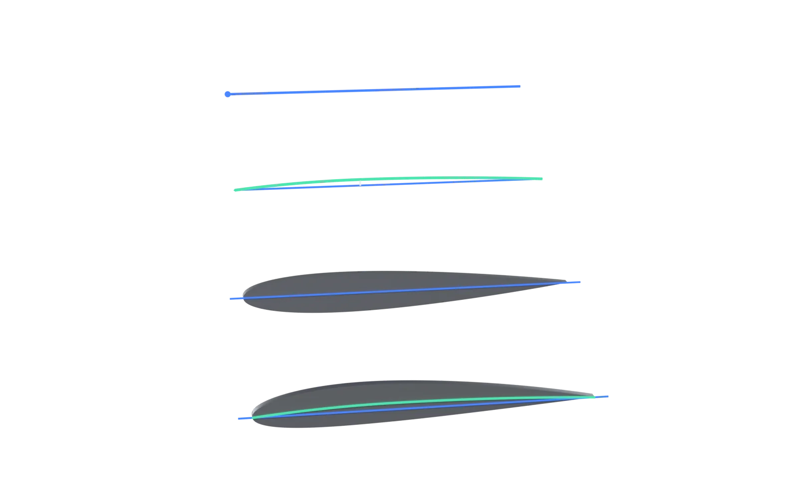
- 1Chord line
- 2+ Mean camber line
- 3+ Thickness (NACA 0012)
- 4= NACA 2412 airfoil
The NACA 4-digit equations
With x as a fraction of the chord, m the maximum camber and p its position (0.02 and 0.4 for NACA 2412), the mean camber line is two parabolas that meet at x = p:
The thickness distribution for a thickness ratio t (0.12 here), from Abbott and von Doenhoff, peaks at 30% of the chord:
The upper and lower surfaces then sit on either side of the camber line, perpendicular to it:
The last coefficient -0.1015 leaves a thin open trailing edge; -0.1036 closes it, which is what this page's model and most CFD meshes use. The leading-edge radius is 1.1019 t² of the chord, centred on a line through the leading edge along the camber slope.
5-digit (for example NACA 23012): the first digit times 3/2 is the design lift coefficient in tenths (2 → 0.3), the next two digits halved give the position of maximum camber in percent of the chord (30 → 15%), and the last two are the thickness (12%). 6-series (for example NACA 65-415): the "6" is the series, the "5" is the position of minimum pressure in tenths of the chord for the basic symmetric section at zero lift, the "4" after the dash is the design lift coefficient in tenths, and the last two digits are the thickness in percent.
Types of airfoils
The main types of airfoils are symmetric, cambered (from mildly to highly cambered), forward-cambered 5-digit sections, laminar-flow sections such as the NACA 6-series, supercritical airfoils for transonic jets, and reflexed airfoils whose camber line is altered toward the trailing edge to cut the pitching moment, at some cost in maximum lift (NACA Report 460). The FAA sums it up: "The weight, speed, and purpose of each aircraft dictate the shape of its airfoil."
All drawn to the same scale from the NACA equations (4- and 5-digit) and the UIUC airfoil coordinate database (64A010, SC(2)-0714). The dashed line is y = 0. Reflexed sections are described but not drawn.
Which airfoils do real aircraft use?
Light aircraft mostly fly NACA sections: the Cessna 172 uses NACA 2412 at the wing root, the Piper Cherokee a NACA 65-415 laminar-flow section and the Beechcraft Bonanza the 5-digit NACA 230 series. Airliners use their makers' own transonic sections.
| Aircraft | Wing root airfoil | Wing tip airfoil |
|---|---|---|
| Cessna 172 Skyhawk (1973 on) | NACA 2412 | NACA 2412 mod |
| Cessna 150 | NACA 2412 | NACA 0012 |
| Piper PA-28 Cherokee | NACA 65-415 | NACA 65-415 |
| Beechcraft Bonanza (35, 36) | NACA 23016.5 | NACA 23012 |
| Beech Super King Air 300 | NACA 23018 | NACA 23012 |
| Glasflügel Standard Libelle (glider) | Wortmann FX 66-17A II 182 | Wortmann FX 66-17A II 182 |
Source: David Lednicer's Incomplete Guide to Airfoil Usage (UIUC). "Mod" usually means the camber line, the leading edge or the trailing-edge thickness has been changed. Several wings in the guide change section from root to tip. Boeing's 737 and 747 use Boeing's own BAC sections.
The equal transit time myth
A common explanation says the air over the longer upper surface must travel faster to meet the air underneath at the trailing edge. That is wrong. Nothing forces the two streams to meet, and the air over the top of a lifting airfoil reaches the trailing edge first. In this page's own flow solution, two parcels released side by side upstream of the nose, one just above and one just below the stagnation streamline, arrive at the trailing edge 0.30 c/V apart in time at 5° and 0.51 c/V at 10°, the upper one first: about 9 ms ahead for a 1.5 m chord at 50 m/s. The FAA points out that "many lifting airfoils do not have an upper surface longer than the bottom, as in the case of symmetrical airfoils".
Look at the streamlines in the 5° and 10° frames: the air ahead of the airfoil rises to meet it (upwash) and leaves the trailing edge angled down. That turning of the flow, with lower pressure above and higher pressure below, is the lift. As the FAA puts it, "the production of lift is much more complex than a simple differential pressure between upper and lower airfoil surfaces."
Airfoil interview and viva questions
Where is the centre of pressure of a cambered airfoil, and why does it move?
It is where the resultant aerodynamic force acts. On a cambered section the pitching moment about the aerodynamic centre stays roughly constant while lift changes, so x_cp = 0.25 - c_m,c/4 / c_l moves forward as lift rises. For NACA 2412 the panel method gives 46% chord at 0°, 32% at 5° and 30% at 10°. That travel is why designers use the aerodynamic centre, not the centre of pressure, for stability work.
What lift-curve slope does thin-airfoil theory predict, and how close is it to reality?
2π per radian, about 0.11 per degree, for any thin airfoil. For NACA 2412 that gives c_l = 2π(α + 2.08°): 0.78 at 5°. The inviscid panel method, which includes thickness, gives 0.86. XFOIL, which adds the boundary layer, gives 0.81 at a Reynolds number of 1 million: the boundary layer takes back most of what thickness adds.
How is the angle of attack different from the angle of incidence?
The angle of attack is between the chord line and the relative wind and changes all through a flight. The angle of incidence is between the wing's chord line and the aircraft's longitudinal axis; the FAA says it is in most cases a fixed, built-in angle.
Why are NACA 4-digit thickness ordinates laid perpendicular to the camber line, and what does that do at the nose?
So that the thickness distribution wraps the same way around any mean line, as NACA Report 824 specifies. A side effect is that the cambered section's nose sits slightly ahead of and above the chord line's leading-edge point, because the leading-edge radius is centred on a line along the camber slope.
Why do supercritical airfoils have a flat upper surface?
On a jet airliner the air over the upper surface goes supersonic and ends in a shock wave that adds drag. NASA's supercritical sections use a large leading-edge radius, reduced curvature over the middle of the upper surface and strong aft camber, which gives a flat pressure distribution on top and pushes the drag rise to a higher Mach number.
About this 3D model
A teaching model, not a particular wing: a straight NACA 2412 segment with a 1 m chord, built in Blender from the NACA equations with a closed trailing edge (240 surface panels). The pressure colours and streamlines come from an inviscid panel solution at each angle; the streamlines are traced from it with a fourth-order Runge-Kutta integrator. The real Cessna 172 wing changes to a modified 2412 at the tip; this segment does not. Every number on this page is checked by a script against the NACA formulas, thin-airfoil theory, two independent panel methods and the XFOIL polars from Airfoil Tools.
Related Skill-Lync courses and reading
- Computational Fluid Dynamics coursesEvery Skill-Lync CFD course in one place: from flow basics to external aerodynamics in ANSYS Fluent, CONVERGE and OpenFOAM.
- Master's Certification in CFDA long programme that includes airfoil and external-flow projects, meshing and turbulence modelling.
- NACA airfoil calculator: coordinates, plotter, lift by thin-airfoil theory and the panel method
- How does an airfoil work? Lift, angle of attack and NACA codes explained
- Nomenclature of an airfoil model
- Airfoil simulation: plotting lift and drag coefficients at different angles of attack
- Fluid mechanics book, chapter 8: boundary layer, drag and lift
- Drag force calculator
- Turbocharger in 3D: the other airfoils in a car, compressor and turbine blades
- More parts in 3D: all engineering components
FAQs
What are the parts of an airfoil?
An airfoil has a leading edge (the rounded front), a trailing edge (the thin rear), an upper surface and a lower surface. Its geometry is described by the chord line joining the two edges, the chord length, the mean camber line halfway between the surfaces, the maximum camber and maximum thickness with their positions along the chord, and the leading-edge radius. In flight, the angle of attack, relative wind, centre of pressure and aerodynamic centre complete the terminology.
What is the difference between the chord line and the mean camber line?
The chord line is a straight line from the leading edge to the trailing edge. The mean camber line is the curved line halfway between the upper and lower surfaces. On a symmetric airfoil the two are the same line; on a cambered airfoil the camber line arches above the chord line, and the largest gap between them is the camber.
What does NACA 2412 mean?
In the NACA 4-digit series the first digit is the maximum camber in percent of the chord (2%), the second is its position in tenths of the chord from the leading edge (0.4, i.e. 40%), and the last two are the maximum thickness in percent of the chord (12%). NACA 2412 is the wing-root section of the Cessna 172 and 150.
What is the angle of attack of an airfoil?
The angle between the airfoil's chord line and the relative wind (the direction of the oncoming air). It is not the same as the angle of incidence, which is the fixed angle between the wing's chord line and the aircraft's longitudinal axis. Lift grows roughly linearly with the angle of attack until the critical angle, where the airfoil stalls.
At what angle of attack does an airfoil stall?
At its critical angle of attack. The FAA says this varies from approximately 16° to 20° depending on the aircraft's design, and that a given aircraft always stalls at the same angle of attack regardless of airspeed or weight. For NACA 2412 alone, XFOIL predicts the maximum lift at 16.5° at a Reynolds number of 1 million, and at 14.25° at 200,000.
Why does a cambered airfoil produce lift at zero angle of attack?
Because its zero-lift angle is negative: the camber turns the flow downward even when the chord line points straight into the wind. Thin-airfoil theory gives a zero-lift angle of -2.08° for NACA 2412, and NACA's wind-tunnel tests in Report 460 measured -1.7°. A symmetric airfoil like NACA 0012 has a zero-lift angle of 0°.
Is it true that air over the top must meet the air underneath at the trailing edge?
No. This 'equal transit time' idea is a common wrong explanation. The FAA points out that many lifting airfoils do not have a longer upper surface at all, for example symmetric airfoils at an angle of attack. In reality the air over the upper surface of a lifting airfoil arrives at the trailing edge well before the air underneath. Lift comes from the airfoil turning the flow, which sets up lower pressure above and higher pressure below.
Sources
- FAA Pilot's Handbook of Aeronautical Knowledge, ch. 4: Principles of Flight (airfoil, leading and trailing edge, chord line, camber, centre of pressure, pressure distribution) · ch. 5: Aerodynamics of Flight (angle of attack, lift and drag directions, stall, critical angle 16° to 20°)
- FAA Aviation Maintenance Technician Handbook (FAA-H-8083-31B) (camber, angle of incidence vs angle of attack)
- NACA Report 824, Abbott, von Doenhoff and Stivers, Summary of Airfoil Data (1945) (4-digit, 5-digit and 6-series numbering, thickness perpendicular to the mean line, leading-edge radius, aerodynamic centre)
- NACA Report 460, Jacobs, Ward and Pinkerton (1933) (rectangular aspect-ratio-6 wings in the variable-density tunnel: NACA 2412 zero-lift angle -1.7°, maximum lift 1.59; NACA 0012: 0.0°, 1.53; Reynolds number about 3 million)
- NASA TP-2969, Harris, NASA Supercritical Airfoils (1990) · UIUC Airfoil Coordinates Database (SC(2)-0714, NACA 64A010)
- D. Lednicer, The Incomplete Guide to Airfoil Usage (aircraft root and tip sections)
- Airfoil Tools XFOIL polars: NACA 2412 at Re 1,000,000 and 200,000 (Ncrit 9)
- I. H. Abbott and A. E. von Doenhoff, Theory of Wing Sections (Dover, 1959): the 4- and 5-digit equations · J. D. Anderson, Fundamentals of Aerodynamics, ch. 4: thin-airfoil theory (NACA 2412 αL=0 = -2.077°, cm,c/4 = -0.053) · A. M. Kuethe and C.-Y. Chow, Foundations of Aerodynamics: panel methods