


Modified on
Understanding Frequency Analysis in SolidWorks FEA

Skill-Lync
Welcome back to our series on Finite Element Analysis (FEA) using SolidWorks! When designing a structure or component, understanding how it will respond to external forces is critical. One of the essential analyses you can perform to assess this is frequency analysis, which helps in determining the vibration characteristics of the structure.
In this blog, we will explore the importance of frequency analysis, explain key concepts like natural frequency and resonance, and walk through a practical example using SolidWorks FEA analysis.
Why Perform Frequency Analysis?
Before diving into the SolidWorks FEA tutorial for frequency analysis, let’s answer the question: Why perform frequency analysis in the first place?
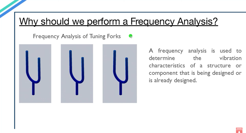
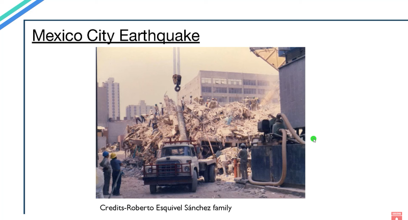
Frequency analysis is used to determine the vibration behavior of a structure when it is subjected to external forces. Every physical structure has a natural frequency at which it tends to vibrate. When an external force matches this natural frequency, resonance occurs. This can result in significant amplification of the vibrations, potentially causing damage. The infamous example of this destructive phenomenon is the 1985 Mexico City earthquake, where buildings with 6 to 15 floors were severely damaged because their natural frequency matched that of the earthquake.
Understanding a structure’s natural frequency allows engineers to design systems that avoid resonant conditions, enhancing the safety and performance of the product.
Choosing the Right Solver in SolidWorks FEA
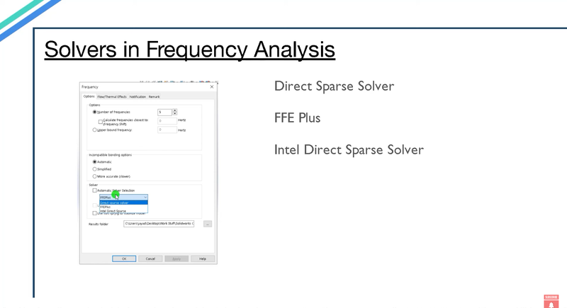
In SolidWorks FEA analysis, there are several solvers available to perform a frequency analysis:
- Direct Sparse Solver: Ideal for multi-area contact problems.
- FF+ Solver: Efficient for large problems with over 100,000 degrees of freedom.
- Iterative Direct Sparse Solver: Useful when materials with vastly different properties are used, such as steel and nylon.
You can either manually select the solver based on the problem or let SolidWorks choose it automatically.
Frequency Analysis in Action: A Support Bracket Example
Let’s consider the frequency analysis of a support bracket to bring these concepts into action. In this example, we compare three different support brackets:
- A normal bracket
- A thicker bracket
- A bracket with a stiffener
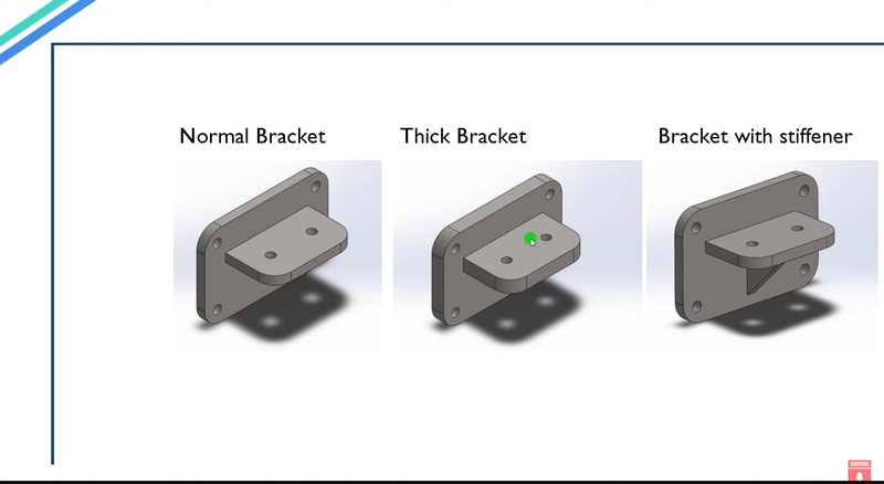
We want to determine which of these designs offers the best resistance to vibrations. Using the finite element method mesh, we first break the model into smaller elements and run the simulation for each bracket in SolidWorks FEA.
Basic Steps in Finite Element Analysis for Frequency
When performing frequency analysis in SolidWorks FEA, there are several fundamental steps involved. These are also part of the basic steps in finite element analysis for any problem:
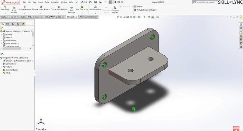
1. Creating the Model: Start by designing the model in SolidWorks. For example, we might model a simple support bracket.
2. Material Selection: After creating the model, apply material properties. The choice of material affects both the stiffness and mass, which in turn influences the natural frequency.
3. Applying Fixtures: Fixtures define the boundary conditions, specifying how the model is constrained. For instance, you may fix the holes in the bracket to simulate how it is attached to other structures.
4. Applying Loads: In a frequency analysis, external loading is typically not the source of vibration, but it can be included if the component experiences static pre-loading in real-world conditions. In some cases, no external load is needed.
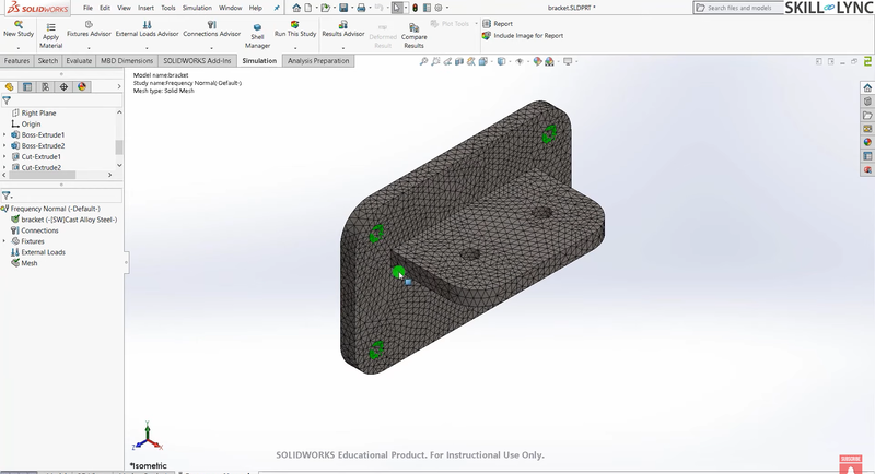
5. Mesh Generation: This is one of the most crucial steps in finite element analysis. By breaking down the model into smaller elements, the finite element method mesh allows the software to compute how each part of the structure responds to forces. Finite element mesh generation, including whether you choose 1D, 2D, or 3D elements, greatly influences the accuracy of the results.
6. Running the Simulation: Once the model is set up with the material, fixtures, loads, and mesh, you can run the frequency analysis. SolidWorks will compute the natural frequencies and mode shapes.
7. Reviewing Results: After the analysis, review the results to check the mode shapes and the corresponding resonance frequencies. You can animate the mode shapes to visualize how the structure will vibrate at each natural frequency.
These steps form the foundation of any SolidWorks FEA analysis and are crucial for a variety of simulations, whether you’re studying vibrations, structural strength, or thermal behavior.
Results
The normal bracket shows a resonance frequency of approximately 1,755 Hz.
The thicker bracket has a higher resonance frequency, around 2,480 Hz, because the added mass and stiffness increase its resistance to vibration.
The bracket with a stiffener achieves the best result, with a resonance frequency of 2,486 Hz, while using less material than the thicker bracket.
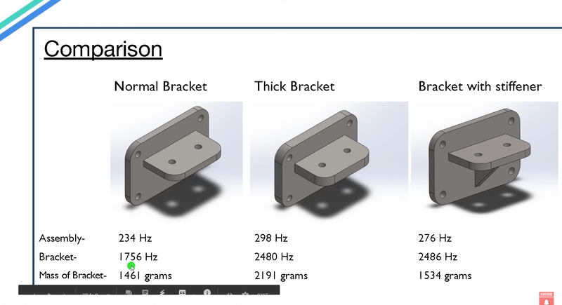
These results highlight how small design changes, like adding a stiffener, can improve performance while reducing material costs. By performing these analyses, we can optimize designs for both performance and cost efficiency.
Conclusion: Mastering Frequency Analysis in SolidWorks FEA.
Frequency analysis is a powerful tool in finite element analysis that helps engineers predict how a structure will react to external forces and avoid potential resonance disasters. By following the basic steps in FEA—from creating the model to running the simulation—you can gain invaluable insights into the behavior of your designs.
For those looking to deepen their understanding of frequency analysis and other simulations, consider enrolling in a SolidWorks FEA course. A structured SolidWorks FEA tutorial can equip you with the knowledge and hands-on skills necessary to perform accurate and efficient simulations in real-world applications.
Stay tuned for more topics in this SolidWorks FEA course as we dive deeper into the world of finite element analysis, mesh generation, and advanced simulations!
This blog is part of our ongoing series on FEA Simulations using SolidWorks.
If you missed the previous posts, check them out here.
Would you like to have a more interactive demonstration of the above concepts?
Skill-Lync has released a Free Comprehensive Course covering FEA with SolidWorks in detail! Check it out here.
Right from the user interface's fundamentals, menus and options, this course covers most aspects of the tool from a practical perspective.
It even includes a certificate to add to your resume after completion!
Check out our hands-on course today and add SolidWorks to your list of skills!
Let’s get #IndustryReady together, one skill at a time!
Author
Uma Maheswari K
Author
Skill-Lync
Subscribe to Our Free Newsletter

Continue Reading
Related Blogs
Explore the fundamentals of vehicle dynamics and ultimate trends in the field from design and modeling to control with Skill Lync's exclusive course on the subject. Read about how Skill-Lync's CAE courses can help you get employed.
28 Jul 2020
In this article, we will briefly discuss the working, applications, and features of the one-dimensional systematic simulation tool, GT-Power, in Emission Control Strategy, engine calibration, hybrid vehicle modeling. Read about how Skill-Lync's CAE courses can help you get employed.
28 Jul 2020
This article offers a brief introduction to the globally accepted standard of Geometric Dimensioning and Tolerancing, and its importance for the entire manufacturing process. Read about how Skill-Lync's CAE courses can help you get employed.
28 Jul 2020
In this blog we will read about Going a step into Biomechanics and how Skill-Lync's CAE course will help you get employed.
09 May 2020
The powertrain is the most prominent source of vibrations that affects the driving experience for the people on board. This blog from Skill-Lync examines these vibrations to help enhance that experience.
21 Aug 2020
Author
Skill-Lync
Subscribe to Our Free Newsletter
Continue Reading
Related Blogs
Explore the fundamentals of vehicle dynamics and ultimate trends in the field from design and modeling to control with Skill Lync's exclusive course on the subject. Read about how Skill-Lync's CAE courses can help you get employed.
28 Jul 2020
In this article, we will briefly discuss the working, applications, and features of the one-dimensional systematic simulation tool, GT-Power, in Emission Control Strategy, engine calibration, hybrid vehicle modeling. Read about how Skill-Lync's CAE courses can help you get employed.
28 Jul 2020
This article offers a brief introduction to the globally accepted standard of Geometric Dimensioning and Tolerancing, and its importance for the entire manufacturing process. Read about how Skill-Lync's CAE courses can help you get employed.
28 Jul 2020
In this blog we will read about Going a step into Biomechanics and how Skill-Lync's CAE course will help you get employed.
09 May 2020
The powertrain is the most prominent source of vibrations that affects the driving experience for the people on board. This blog from Skill-Lync examines these vibrations to help enhance that experience.
21 Aug 2020
Related Courses


