APPLICATION OF SOIL LOAD ON TOP OF FOOTING USING PARTIAL PRESSURE ON PLATES IN STAAD.PRO
The bridge foundation is the base of a bridge that transmits the loads from the substructure to the supporting strata. It must be sufficiently deep so that it is not affected by the scour caused by the flow in the river.
 Navin Baskar·25 Jan 2023·2 min read
Application Of Soil Load On Top Of Footing Using Partial Pressure On Plates In Staad.PRO
The bridge foundation is the base of a bridge that transmits the loads from the substructure to the supporting strata. It must be sufficiently deep so that it is not affected by the scour caused by the flow in the river. The foundations of a bridge are particularly critical because they must support the entire weight of the bridge and the traffic loads it will carry.
Loads due to soil on top of footing using partial pressure
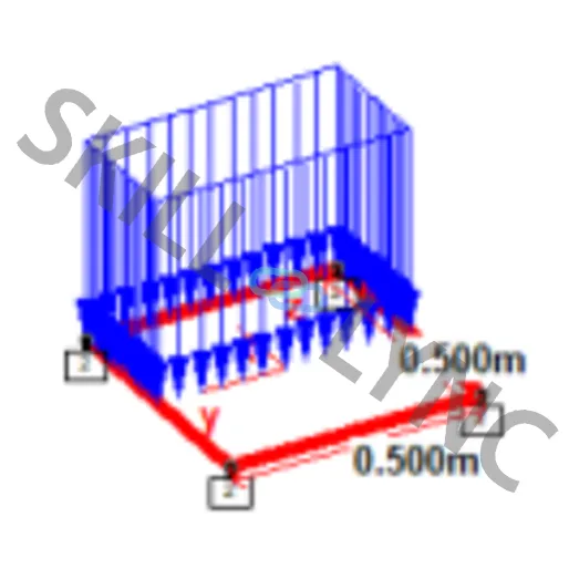
The abutment is modeled in the below STAAD model using plate elements of size 0.5x0.5m. On application of soil loads at the top of the footing, it is not possible to be applied as pressure acting fully on the plate, since half of the foundation plate will be under the abutment wall.
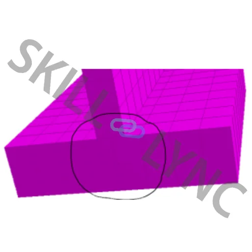
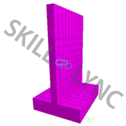
To apply the soil loads acting on top of the foundation, the following procedure is followed.
- Select the specific plate where load is to be applied
- Check the local axes of the plate (Shift+T to check the local axes)
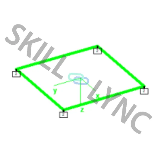
- Here the local axis x and y direction should be noted.
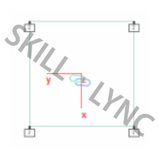
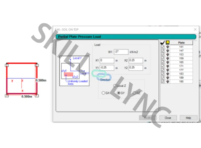
- The coordinates need to be provided as the per local axis of the plate. It is assumed that the (0,0) is in the middle of the plate and the coordinates in the local axis with reference to the center should be calculated.
- In this example the thickness of the abutment wall is 0.5m and the foundation is divided into plates of size 0.5 x 0.5 m.
Procedure
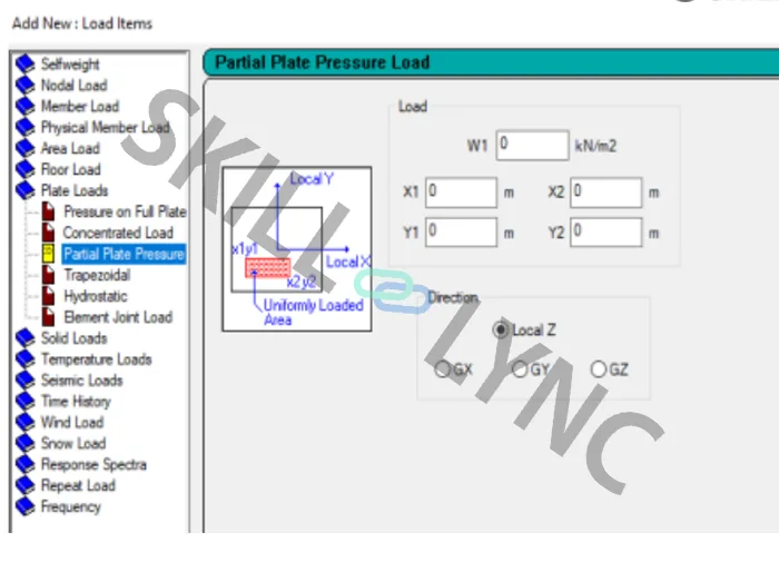
- Load cases details >> Add >> Primary >> Change Title >> Soil on top >> Add • Click on the load case >> Add >> Plate loads >> Partial plate pressure Load >> Specify the load intensity & the plate coordinates calculated above
- Change the direction to GY (since the load is applied in Y direction here)
- Select the required plates and assign to selected plates >> Assign