


Modified on
Simulating Transient Flow Over a Cylinder in SolidWorks: A Comprehensive Guide

Skill-Lync
Welcome back to the CFD Simulation Using SolidWorks blog series! I hope you're all doing great. In today’s blog, we’re diving into a transient flow simulation — specifically, simulating flow over a cylinder. This will give you a hands-on look at how time-dependent simulations work, and how you can set up one using SolidWorks Flow Simulation.
Step 1: Creating the Cylinder Geometry
To get started, the first step is to create the geometry of a cylinder over which we will simulate the flow.
- Create a New Part: Start by creating a new part in SolidWorks.
- Sketch a Circle: On the front plane, draw a circle with a radius of 0.02 meters.
- Extrude the Circle: Extrude the circle to form a cylinder. Set the length of the cylinder to 0.05 meters.
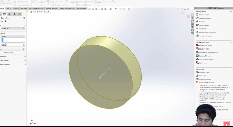
This simple geometry will be the basis of our flow over cylinder simulation.
Step 2: Setting Up the Flow Simulation
Once the cylinder geometry is ready, we’ll move on to setting up the flow simulation.
- Start SolidWorks Flow Simulation: Open the Flow Simulation Wizard.
- Name the Project: Let’s name the project "Flow Over a Cylinder".
- Unit Systems and Analysis Type: Keep the default unit systems and move forward. In the analysis type, select External Flow Simulation since the flow will take place around the cylinder, and make sure to choose Time-dependent simulation.
What is a time-dependent (transient) simulation?
A transient simulation solves the flow equations as a function of time. Unlike steady-state simulations that assume conditions are constant over time, transient simulations capture how the flow evolves with time, making them ideal for cases where time-varying behavior is important.
For this simulation, we’ll run it for 0.1 seconds, with an output time step of 0.01 seconds. This means that throughout the simulation’s duration, we will get 10 outputs (snapshots of the flow).
- Select the Fluid: In the next step, select air as the default fluid. We’ll use the default flow models for now.
Step 3: Setting the Computational Domain
Because this is an external flow simulation, SolidWorks will create a bounding box, which defines the limits of our computational domain. Here’s how to set it up:
- Direction of Flow: Ensure that the flow enters the domain along the X-axis. This way, the air will flow over the cylinder as intended. The velocity in the Y and Z directions should be set to zero to constrain the flow to the X direction.
- Computational Domain: The computational domain is where the simulation will take place. It’s the virtual space where the fluid (air) will flow into, over the cylinder, and exit out the other side.
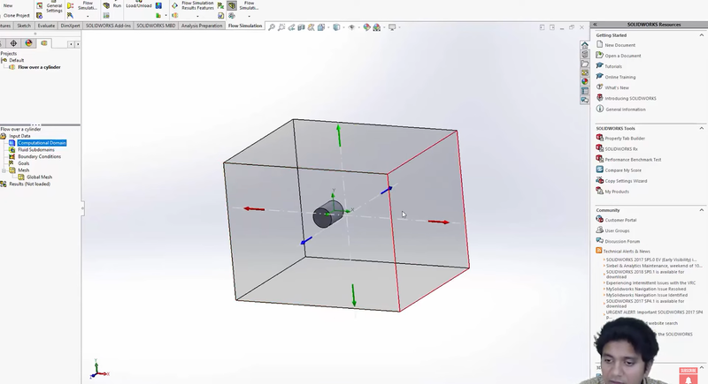
Now that the domain is set, you’ll see the cylinder inside this virtual domain box. The air will enter the domain, flow over the cylinder, and exit on the other side.
Step 4: Running the Initial Simulation
Let’s proceed with running a simple simulation to check if everything is set up correctly.
- Run the Simulation: Click on the Run button and start the calculation. SolidWorks will compute the flow over the cylinder. This initial simulation should only take a minute or so to complete.
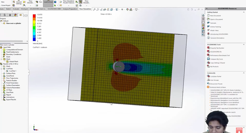
- Check the Results: Once the simulation is complete, let’s take a look at the results. We’ll start by creating a cut plane through the middle of the cylinder to visualize the flow.
- Adjust the Cut Plane: Initially, the cut plane might not be positioned in the center of the cylinder. Use the Front View to move the cut plane so that it slices through the middle.
- Visualizing the Flow: Once the cut plane is correctly positioned, we can view the velocity distribution across the plane. This shows us how the air moves over the cylinder at different speeds.
Step 5: Animating the Transient Simulation
Since this is a time-dependent simulation, we can create an animation to visualize how the flow develops over time.
1. Create an Animation: Use the Animation Wizard to create an animation for the transient simulation. Set the animation time to 10 seconds. In this case, we’re not interested in rotating the model, so keep the focus on the simulation results.
2. Load the Simulation Data: When prompted, load the transient simulation data. This data was generated during the simulation, capturing how the flow evolves over time, from 0 seconds to 0.1 seconds.
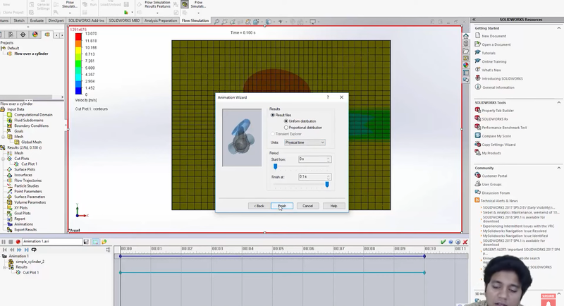
3. Play the Animation: Now, you can watch the flow develop. As the animation plays, you’ll notice the velocity field gradually building up over time. The flow starts from zero, then accelerates around the cylinder, and eventually stabilizes.
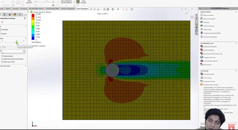
This visualization gives us a clear view of how the flow evolves, as well as the development of the velocity field over time.
Step 6: Refining the Simulation
Before we finalize the results, there are a few important aspects we need to address:
- Analyze the Results: As engineers, it’s important to validate your CFD results. Do the results make sense based on physical principles? For example, is the velocity field behaving as expected? These are questions you should ask yourself during analysis.
- Check for Grid Dependency: It’s always a good idea to refine your mesh (computational grid) to check for grid dependency. This means running the simulation with a finer grid to see if the results change. Finer grids generally lead to more accurate results, but they also increase computational time.
- Edit the Base Mesh: Go to the base mesh settings and refine the grid as much as possible. If you’re using a laptop, you may be limited in how much you can refine the grid but try to go as fine as your system allows.
- Run a Grid Dependency Test: After refining the grid, re-run the simulation to see if the results change. This will help ensure that your solution is accurate and not dependent on a coarse grid.
Step 7: Next Steps and Project
To further enhance your understanding of this problem, here’s a challenge for you:
- Calculate the Reynolds Number: Based on the cylinder dimensions and flow conditions, calculate the Reynolds number for the flow over the cylinder. The Reynolds number is a key parameter in determining whether the flow is laminar or turbulent.
- Increase the Reynolds Number: Once you’ve calculated the Reynolds number, set up two or three additional simulations where you increase the Reynolds number by a factor of 10 and 100. See how this change affects the flow structure around the cylinder.
- Refine the Mesh: As mentioned earlier, try to make the mesh finer by adjusting the grid settings. Conduct a grid refinement study to check how mesh resolution impacts the simulation results.
- Document Your Results: Once you’ve completed these additional simulations, document your findings. This will be a valuable exercise in understanding how flow behaves under different conditions and mesh resolutions.
Conclusion
In this blog, we walked through the process of setting up a transient flow simulation in SolidWorks, focusing on flow over a cylinder. We explored how to set up the geometry, apply boundary conditions, run the simulation, and visualize the results through animations. We also covered the importance of mesh refinement and grid dependency tests to ensure accurate results.
By following these steps, you’ll gain a deeper understanding of how transient simulations work and how to analyze complex flow behavior in CFD using SolidWorks.
Hope you found this blog helpful. Stay tuned for more exciting topics in our CFD Simulation Using SolidWorks series.
This blog is part of our ongoing series on CFD Simulations using SolidWorks.
If you missed the previous posts, check them out here.
Would you like to have a more interactive demonstration of the above concepts?
Skill-Lync has released a FREE comprehensive course covering CFD Simulations using SolidWorks in detail! Check it out here.
Right from the user interface's fundamentals, menus and options, this course covers most aspects of the tool from a practical perspective. It even includes a certificate to add to your resume after completion!
Check out our hands-on course today and add SolidWorks to your list of skills!
Let’s get #IndustryReady together, one skill at a time!
Author
Uma Maheswari K
Author
Skill-Lync
Subscribe to Our Free Newsletter

Continue Reading
Related Blogs
Explore the fundamentals of vehicle dynamics and ultimate trends in the field from design and modeling to control with Skill Lync's exclusive course on the subject. Read about how Skill-Lync's CAE courses can help you get employed.
28 Jul 2020
In this article, we will briefly discuss the working, applications, and features of the one-dimensional systematic simulation tool, GT-Power, in Emission Control Strategy, engine calibration, hybrid vehicle modeling. Read about how Skill-Lync's CAE courses can help you get employed.
28 Jul 2020
This article offers a brief introduction to the globally accepted standard of Geometric Dimensioning and Tolerancing, and its importance for the entire manufacturing process. Read about how Skill-Lync's CAE courses can help you get employed.
28 Jul 2020
In this blog we will read about Going a step into Biomechanics and how Skill-Lync's CAE course will help you get employed.
09 May 2020
The powertrain is the most prominent source of vibrations that affects the driving experience for the people on board. This blog from Skill-Lync examines these vibrations to help enhance that experience.
21 Aug 2020
Author
Skill-Lync
Subscribe to Our Free Newsletter
Continue Reading
Related Blogs
Explore the fundamentals of vehicle dynamics and ultimate trends in the field from design and modeling to control with Skill Lync's exclusive course on the subject. Read about how Skill-Lync's CAE courses can help you get employed.
28 Jul 2020
In this article, we will briefly discuss the working, applications, and features of the one-dimensional systematic simulation tool, GT-Power, in Emission Control Strategy, engine calibration, hybrid vehicle modeling. Read about how Skill-Lync's CAE courses can help you get employed.
28 Jul 2020
This article offers a brief introduction to the globally accepted standard of Geometric Dimensioning and Tolerancing, and its importance for the entire manufacturing process. Read about how Skill-Lync's CAE courses can help you get employed.
28 Jul 2020
In this blog we will read about Going a step into Biomechanics and how Skill-Lync's CAE course will help you get employed.
09 May 2020
The powertrain is the most prominent source of vibrations that affects the driving experience for the people on board. This blog from Skill-Lync examines these vibrations to help enhance that experience.
21 Aug 2020
Related Courses


