NHAI High-Speed Corridor Guidelines: What Changes in Highway Design
NHAI's Policy Circular 10.2.51/2026 of 20 September 2026 sets one standard for 4/6-lane access-controlled national highways: no at-grade junctions or median openings, a 60-70 m right of way, a 12 m depressed median, intermediate sight distance on crests, mandatory machine-aided construction, free-flow tolling and drainage plans. Here is what it requires, what is new against IRC:SP:84, a worked crest-curve example, and what it means for civil engineers.

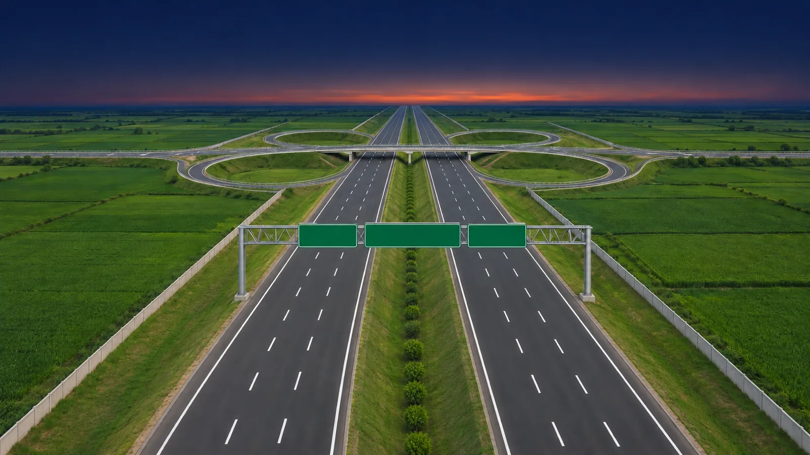
The National Highways Authority of India (NHAI) has issued a single design rulebook for its new high-speed corridors: four- and six-lane national highways with full access control that are not formally expressways. Policy Circular No. 10.2.51/2026, dated 20 September 2026, makes the rules mandatory for all of NHAI's technical divisions. It bans at-grade junctions and median openings, sets a 60 m or 70 m right of way by traffic, requires a depressed median at least 12 m wide (or a flush one at least 5 m wide), demands longer crest curves, and makes machine-aided construction compulsory for embankments and pavements. It also builds free-flow tolling, drainage, water harvesting and median drip irrigation into the project report stage.
The Press Information Bureau (PIB) summarised the circular on 21 and 24 September 2026, and the second release resurfaced in news feeds this week. Below, from the circular itself: what it requires, how it differs from the four-lane manual (IRC:SP:84), a worked crest-curve example, and what it means for civil engineering jobs.
Key numbers at a glance
- 20 Sep 2026: NHAI Policy Circular No. 10.2.51/2026 issued, "for mandatory adoption by all Technical Divisions of NHAI". It applies to all upcoming 4/6-lane greenfield and brownfield access-controlled national highways.
- 50,000 km: the length of access-controlled high-speed corridors in the Ministry of Road Transport and Highways (MoRTH) roadmap. The circular says "by 2036-37"; PIB frames it under Viksit Bharat 2047 (PIB, 21 Sep 2026).
- 60 m / 70 m: minimum right of way (ROW) for up to 15,000 PCU, and for 15,000-40,000 PCU (circular, para 5.2).
- 12 m: minimum depressed median, against 7 m in IRC:SP:84-2014 for open country. Raised medians are not allowed.
- 360 m: intermediate sight distance (ISD) that new crest curves must now provide at 100 km/h, twice the 180 m stopping sight distance (IRC:66; IRC:SP:84). In our worked example this makes a crest curve 1.83 times longer.
Courses: the geometry in this post is taught in Skill-Lync's Geometric Design Fundamentals course. To build these alignments in software, see Roadway Design with OpenRoads.
What did NHAI issue, and when?
On 20 September 2026 NHAI issued Policy Circular No. 10.2.51/2026, "Guidelines for design and development of Access Controlled National Highways (High-Speed Corridors – other than Expressways)". It is an 18-page bilingual document, including three annexures, and every NHAI technical division must follow it when preparing detailed project reports (DPRs). PIB summarised it in two releases, on 21 and 24 September 2026.
- The circular (confirmed). Signed by NHAI's Chief General Manager (Coordination) and addressed to all NHAI offices. We read the signed scan hosted by the Highway Operators Association of India (HOAI), as we could not retrieve it from nhai.gov.in. Every design number here comes from that scan or the IRC codes in the sources.
- PIB, 21 September 2026 (confirmed). Right-of-way widths, interchanges, advance notice of exits and the boundary wall.
- PIB, 24 September 2026 (confirmed). "NHAI Guidelines to Strengthen Technology Integration and Sustainability in Development of High-Speed National Highway Corridors": traffic forecasting, machine-aided construction, free-flow tolling, landscaping, drip irrigation and drainage.
Why did NHAI need separate rules for high-speed corridors?
NHAI needed them because a gap had opened between its two existing rulebooks. Expressways follow IRC:SP:99, and ordinary four- and six-laning follows IRC:SP:84 and IRC:SP:87. Fully access-controlled national highways that are not expressways had no standard of their own. In the circular's words, "even for the same corridor traversing through different states, the standards adopted also differs from State to State."
The circular splits high-speed corridors into two categories:
- Category (i): expressways. These are designed to IRC:SP:99, which sets a design speed of 120 km/h in plain terrain and 100 km/h in rolling terrain.
- Category (ii): national highways with full access control. These follow IRC:SP:84 (four-lane) or IRC:SP:87 (six-lane), plus the extra provisions in the circular. Design speed stays "as per IRC:SP:84/87", which in plain and rolling terrain means a ruling 100 km/h and a minimum 80 km/h. The circular's own lane tables are written for exactly those two speeds.
Think of category (ii) as a four-lane highway that behaves like an expressway: ramps only, land walled off, geometry still built for 100 km/h.
What do the new NHAI guidelines require?
They require a traffic study that sets the lane count for the whole design period, a full access-controlled cross-section with a wide depressed median, grade-separated access only, a fixed set of safety hardware, and four "planning-stage" items. Those four are machine-aided construction, free-flow tolling provisions, a drainage plan and a landscaping plan.
Traffic forecasting and lane configuration
The DPR consultant must model existing, generated, induced and diverted traffic. Freight growth must be tied to economic development. The counts are cross-checked against toll transactions. For freight volumes and the vehicle damage factor (VDF), which converts mixed trucks into standard axle loads for pavement design, the circular asks for data from GST portals and mining departments. The method is IRC:108.
The traffic band then fixes the corridor configuration and the minimum ROW:
| Present traffic (PCU) | Stage development | Minimum ROW |
|---|---|---|
| Up to 15,000 | 4-lane highway, 4-lane structures | 60 m |
| 15,000 to 25,000 | 4-lane highway, 6-lane structures | 70 m |
| 25,000 to 40,000 | 6-lane highway, 6-lane structures | 70 m |
The middle row is the interesting one. Bridges and flyovers are built for six lanes on day one while the road is paved for four. Structures are the costliest part of a highway to widen later, which is the usual reason to build them wide first. The configuration must also stay the same along the whole corridor unless the competent authority approves a change. That clause targets the state-to-state differences the circular complains about.
Cross-section and geometric standards
The table below lists the main design parameters. All of them are minimums or fixed values, and any deviation has to be written into Schedule-D of the contract.
| Parameter | NHAI circular 10.2.51/2026 |
|---|---|
| Access | Fully access controlled; no at-grade intersections; ROW fully fenced |
| Design speed | As per IRC:SP:84/87 (100 km/h ruling, 80 km/h minimum in plain/rolling terrain) |
| Lane width | 3.5 m |
| Median | Depressed: min 12.0 m, with a 0.6 m paved edge strip. Flush: min 5.0 m, with a wire-rope crash barrier at the centre. No raised median. |
| Shoulders | As per the MoRTH circular of 4 June 2024 |
| Ramp design speed | Loop 40-60, semi-direct 60-70, direct 60-80 km/h |
| Ramp width | Minimum 2 lanes plus 0.5 m kerb shyness on each side |
| Sight distance | New roads: ISD only on crest (summit) curves. Valley curves by headlight sight distance. SSD only on existing highways where site constraints rule out more. |
| Embankment slope | 2H:1V |
| Median openings | None. A collapsible median barrier every 5 km for emergency and maintenance vehicles; removable New Jersey barriers not permitted. |
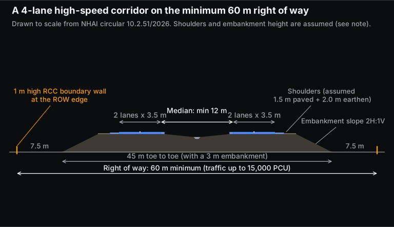
The drawing shows how the 60 m is used. The formation (median, lanes and shoulders) takes 33 m. On a 3 m embankment the 2H:1V side slopes add 6 m on each side, so the road is 45 m wide toe to toe. That leaves 7.5 m on each side for toe drains, the optional 3 m utility corridor that the circular allows in industrial corridors, and the boundary wall. On a higher embankment the slopes eat into that margin. That is why the circular tells consultants to plan land at high fills so that retaining walls are kept to a minimum.
Access, interchanges and exits
Drivers can join or leave only at grade-separated interchanges with ramps. Interchanges go where the corridor crosses an expressway, national highway, state highway or important arterial road likely to generate tollable traffic. They also go on roads leading to ports, airports, multi-modal logistics parks (MMLPs), integrated check posts, industrial areas and major tourist destinations. Other roads cross over or under without ramps. Where harvesters and loaded tractors are common, the underpass height can be 4.5 m. On brownfield (upgrade) projects, side roads can be linked by service roads to the nearest interchange.
Each exit gets a sequence of five advance signs. Full overhead gantry signs stand 5 km and 2 km before each exit, cantilever gantries at 1 km and 500 m, and a butterfly cantilever at the gore (the split point between the ramp and the main road). At the 100 km/h design speed, those signs give a driver 180 s, 72 s, 36 s and 18 s of warning.
The circular also fixes minimum lengths for the speed-change lanes beside each ramp:
| Highway design speed | Ramp curve speed 40 km/h | 50 km/h | 60 km/h | 70 km/h |
|---|---|---|---|---|
| Acceleration lane, 80 km/h | 145 m | 115 m | 65 m | – |
| Acceleration lane, 100 km/h | 285 m | 255 m | 205 m | 110 m |
| Deceleration lane, 80 km/h | 100 m | 90 m | 80 m | 55 m |
| Deceleration lane, 100 km/h | 145 m | 135 m | 120 m | 100 m |
Service roads are required on both sides in built-up stretches, with a combined drain and footpath, and pedestrian facilities to IRC:103-2022. Service and slip roads are designed for at least 20 million standard axles (MSA) or the projected traffic, whichever is more, preferably with rigid (concrete) pavement in urban areas.
Safety hardware
At grade-separated structures and bridges, the median wall continues through the structure with a thrie-beam barrier on top. Thrie-beam metal barriers run 50 m along all four approaches on the median side, 500 mm clear of the edge strip. Where the median is narrower than 9 m, a thrie-beam barrier rated to containment level H-2 (type W3) goes on both sides of the median. In practice that means flush medians, which can be as narrow as 5 m.
Every gore area and split carriageway gets a crash cushion (an impact attenuator), either self-restoring or repairable. Annexure-2 specifies cushions crash-tested to EN 1317-3 and NCHRP-350 test level 3. Delineators are spaced at 30 m on straight sections, lane markings are 150 mm wide and edge lines 200 mm. The 1 m high reinforced-concrete boundary wall along the outer edge of the ROW keeps out encroachment, unauthorised entry and stray cattle. Annexure-3 details it in M20 concrete, 1,000 mm above ground and 350 mm below, on an M15 base.
Technology: machine-aided construction and free-flow tolling
Para 5.16 is headed "Mandatory use of technologies and applications". It requires Automated and Intelligent Machine-aided Construction (AI-MC) for all embankment and pavement work, following MoRTH's guidelines, written into the contract schedules. AI-MC replaces string lines and manual levelling with satellite-positioned machines. In NHAI's pilot on the Lucknow-Kanpur greenfield expressway these were a GPS-aided motor grader, an intelligent compactor and a stringless paver (PIB, 6 February 2025). NHAI listed the expected gains as faster construction, real-time digital records and better control of surface level and compaction. Think of it as the road-building version of CNC machining: the design model drives the machine, and the machine logs what it actually built.
On tolling, the circular says that "in view of the mandate of the Government of India to shift to Multi Lane Free Flow (MLFF) system of tolling, provisions shall accordingly be made". The toll-plaza layout must follow NHAI's own guidelines. MLFF is barrier-less tolling: overhead gantries read FASTag and number plates using automatic number plate recognition (ANPR), so vehicles do not stop. NHAI had MLFF running at at least seven toll plazas by 1 October 2026, from Choryasi in Gujarat to Paranur in Tamil Nadu (PIB, 1 October 2026).
Sustainability: drainage, water harvesting and landscaping
Every DPR must now include a drainage design with defined disposal points. Water-harvesting structures go in interchange loops and at other spots with no natural outlet. Median water flows through precast trapezoidal concrete drains to the nearest culvert or bridge, or out through a half culvert with an RCC chamber.
At underpasses and flyovers, median water may not be dumped into the open area of the structure. It must be carried away and discharged beyond the embankment toe through an RCC chamber and a half-pipe culvert at least 1,200 mm in diameter. PIB says the aim is to prevent waterlogging and damage to the highway around underpasses, flyovers and depressed medians.
Landscaping and planting plans are also drawn at DPR stage, for loops, the space under flyovers and the median. They go into Schedule-C, so they are priced into the contract rather than added later. The median gets drip irrigation.
What is new compared with IRC:SP:84?
Compared with IRC:SP:84, the four-lane manual these corridors otherwise follow, the circular removes at-grade junctions and median openings, widens the depressed median from 7 m to 12 m, and makes ISD the standard on crests. It also adds the boundary wall, five exit signs and the AI-MC requirement. The 60 m minimum ROW for four lanes is unchanged.
| Item | IRC:SP:84-2014 (four-laning) | NHAI circular 10.2.51/2026 |
|---|---|---|
| Junctions | At-grade intersections allowed (section 3.2) | None; ramps at grade-separated interchanges only |
| Median openings | Not closer than 2 km in open country, 500 m in built-up areas | None; collapsible barrier every 5 km for emergencies |
| Median (open country) | Raised min 5.0 m or depressed min 7.0 m | Depressed min 12.0 m or flush min 5.0 m; no raised median |
| Crest sight distance | Desirable 360 m adopted unless Schedule B says otherwise; 180 m SSD as the floor | ISD (360 m) only for new roads; SSD only on constrained existing roads |
| Minimum ROW, 4-lane | 60 m | 60 m (70 m from 15,000 PCU) |
| Boundary | No boundary-wall clause | 1 m RCC wall at the ROW edge, ROW fully fenced |
| Construction technology | No AI-MC requirement | AI-MC mandatory for embankments and pavements |
The sight-distance row deserves a closer look. IRC:SP:84 already calls 360 m the "desirable" value, but it lets a project drop to 180 m wherever the contract's Schedule B says so. The circular removes that option on new crest curves. That has a direct cost in earthwork, which the worked example below puts a number on.
Worked example: how much longer does a crest curve get?
At 100 km/h with grades of +2.5% and −2.5% (the ruling gradient in IRC:SP:84), a crest curve sized for 180 m stopping sight distance needs to be about 368 m long. Sized for the 360 m ISD that the circular now requires, it needs 675 m, which is 1.83 times as long. The curve's midpoint also sits 4.22 m below the point where the two grades meet, instead of 2.30 m.
Step 1: stopping sight distance. IRC:66 adds the distance covered during a 2.5 s perception-reaction time to the braking distance, with a longitudinal friction coefficient of 0.35 at 100 km/h:
IRC rounds this to 180 m, the value in IRC:SP:84's Table 2.7. ISD is defined as twice SSD, so .
Step 2: why ISD is harder on a crest. The two distances are measured differently. SSD is measured from a driver's eye 1.2 m above the road to an object 0.15 m high, such as debris on the road. ISD is measured from 1.2 m to 1.2 m, which is roughly what you need to see an oncoming car's roof. The higher target helps, but the sight line is twice as long, and on a parabolic crest the required length grows with the square of the sight distance.
Step 3: curve length. For a square-parabola crest longer than the sight distance , with eye height , object height and grade change (as a fraction), the minimum length is:
For SSD the denominator is . For ISD it is . With :
Both lengths exceed their sight distances, so the formula applies. The script also checks both answers independently: it casts sight lines across the curve at every driver position and finds the shortest curve that keeps them clear. It returns the same 368.4 m and 675.0 m.
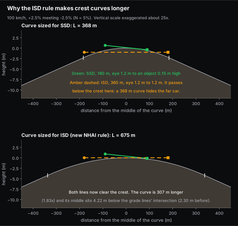
Step 4: what it costs. The ISD curve is 307 m longer. Its midpoint is 4.22 m below the point where the two grades meet (), against 2.30 m for the SSD curve. On a crest in cut, that extra 1.9 m of depth at the centre, spread over a much longer curve, is extra excavation. On a crest over a cross-road, it changes the levels of the structure. A DPR consultant now has to carry that cost on every new crest, and it is the price of letting drivers see a car or a stalled truck well before they reach it.
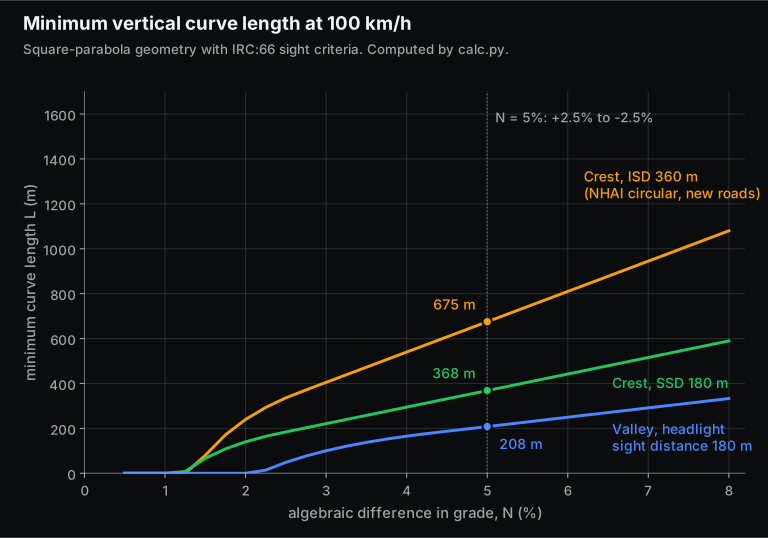
Valley curves are governed by headlights at night, as the circular requires. IRC:66 assumes a headlight 0.75 m above the road with a beam angled 1° upwards, and the beam must light the road for one stopping sight distance:
A check on the exit lanes. If you treat the circular's 120 m deceleration lane (100 km/h highway to a 60 km/h ramp) as constant-rate braking, the implied rate is
That is about 60% of the 3.43 m/s² (0.35 g) emergency braking assumed in the SSD calculation. The 205 m acceleration lane implies 1.20 m/s². These are our simplified averages, not the method behind the table, but they show the lane lengths assume comfortable driving, not hard braking.
What does this mean for civil engineering jobs and skills?
For civil engineers, the circular turns a 50,000 km programme into one standard that every DPR consultant, contractor and NHAI engineer has to design and build to. The work shifts towards interchange and ramp geometry, traffic modelling, drainage design and machine-controlled construction. Engineers who can do highway geometry in software, with the IRC rules behind it, are the ones these projects need.
Here is where the circular creates work, and the skill each area needs:
- Highway geometric design. Every corridor needs ramps, loops, speed-change lanes and longer crest curves, designed to IRC:SP:84/87 plus the circular. The tools are Autodesk Civil 3D and Bentley OpenRoads Designer. Skill-Lync's roadway project course (InfraWorks, Civil 3D and Map 3D) covers this workflow. The fundamentals (sight distance, superelevation, vertical curves) are also GATE CE favourites; see our solved GATE transportation engineering questions.
- Traffic and transport planning. Lane counts now depend on IRC:108 forecasts checked against toll and GST data. That needs engineers who can build and validate traffic models, not just copy growth rates.
- Pavement and earthwork (AI-MC). Machine guidance needs a clean digital 3D design surface for the grader and paver to follow, and it produces data that site engineers must check. Surveyors and quality engineers who understand GNSS positioning, digital terrain models and intelligent-compaction records are new roles on NHAI sites. Our post on drones in construction covers the survey side.
- Drainage and hydrology. A mandatory drainage plan with disposal points, water harvesting and underpass drainage means more hydrology work at DPR stage. Our HEC-RAS course covers the river and channel modelling behind it.
- Structures and safety. Six-lane structures on four-lane roads, median walls, barriers and boundary walls all need structural design and road-safety audit skills.
- ITS and tolling. MLFF gantries and ANPR systems need engineers who understand highway electronics, data and enforcement, a role that sits between civil and electronics.
If you want the whole infrastructure stack (roads, bridges and project management) in one programme, see the Post Graduate Program in Infrastructure Engineering Design and Project Management. For pay ranges in the field, see our civil engineer salary page. For the basics of alignment and cross-sections, start with our road design guide.
What is still unclear?
Several details are not settled by the documents we could read:
- Shoulder widths. The circular points to a MoRTH circular of 4 June 2024 that we could not read, so the shoulders in our cross-section are assumptions.
- Machine-aided construction. AI-MC is required "as per extant guidelines of MoRTH". In February 2025 the government said it was still finalising that policy, so check the current MoRTH document before writing specifications.
- MLFF tolling. The toll-plaza layout must follow NHAI guidelines that the circular does not reproduce.
- Which projects it covers. The circular applies to "upcoming" corridors. It does not say how projects whose DPRs are already under way will be handled.
- Code editions. We compared the circular with the public 2014 edition of IRC:SP:84. IRC has since revised the manual, so project work should use the current edition.
Treat the numbers in this post as a guide to what the guidelines mean, not a substitute for the documents.
Frequently asked questions
What is an access-controlled high-speed corridor in India?
It is a national highway that traffic can enter or leave only at grade-separated interchanges with ramps. It has no at-grade junctions, no median openings and a fenced or walled right of way. NHAI's circular of 20 September 2026 covers the ones that are not expressways: four- and six-lane national highways designed to IRC:SP:84/87 plus extra rules.
How is a high-speed corridor different from an expressway?
Both are fully access controlled. Expressways are designed to IRC:SP:99, at 120 km/h in plain terrain and 100 km/h in rolling terrain. Access-controlled national highways follow the four- and six-lane manuals (ruling design speed 100 km/h in plain and rolling terrain) with the circular's additions, such as the 12 m median and ISD on crests.
Do the NHAI guidelines apply to existing highways?
They apply to all upcoming four- and six-lane greenfield and brownfield access-controlled highways entrusted to NHAI, so a brownfield upgrade of an existing road is covered. Existing highways may keep stopping sight distance on crests where site constraints rule out more. For those projects, service roads can link side roads to the nearest interchange.
What is AI-MC in road construction?
AI-MC stands for Automated and Intelligent Machine-aided Construction. Satellite-positioned machines, such as GPS-aided motor graders, intelligent compactors and stringless pavers, build the embankment and pavement to a digital design and record what they built. NHAI piloted it on the Lucknow-Kanpur expressway, and the circular makes it mandatory for embankments and pavements on these corridors.
Why does the circular insist on intermediate sight distance on crests?
ISD (360 m at 100 km/h) lets a driver see a car-height object at twice the stopping distance, which leaves margin at high speed. The cost is longer curves. In our example with grades of +2.5% and −2.5%, a crest curve grows from 368 m to 675 m.
Sources and further reading
- NHAI, Policy Circular No. 10.2.51/2026: Guidelines for design and development of Access Controlled National Highways (High-Speed Corridors – other than Expressways), 20 September 2026 (signed scan hosted by the Highway Operators Association of India).
- PIB, Ministry of Road Transport & Highways, NHAI Introduces New Guidelines for Design and Development of Access-Controlled High-Speed National Highways, 21 September 2026.
- PIB, Ministry of Road Transport & Highways, NHAI Guidelines to Strengthen Technology Integration and Sustainability in Development of High-Speed National Highway Corridors, 24 September 2026.
- PIB, Ministry of Road Transport & Highways, Use of Automated & Intelligent Machine-Aided Construction System, 6 February 2025.
- PIB, Ministry of Road Transport & Highways, NHAI Rolls out Tamil Nadu's First Barrierless Multi-Lane Free Flow Tolling System, 1 October 2026.
- Indian Roads Congress, IRC:SP:84-2014, Manual of Specifications and Standards for Four Laning of Highways, August 2014 (public copy).
- Indian Roads Congress, IRC:66-1976, Recommended Practice for Sight Distance on Rural Highways (public copy).
- Indian Roads Congress, IRC:SP:99-2013, Manual of Specifications and Standards for Expressways (public copy).