Setting Up Motion Analysis in SolidWorks for Valve, Cam, and Rocker Assembly
Learn how to set up motion analysis in SolidWorks for a valve, cam, and rocker assembly. This guide walks through enabling motion study, adding motors, setting material contacts, and analyzing dynamic motion for a complete simulation.

Welcome back to the Multibody Dynamics using SolidWorks blog series! In this blog, we will explore how to set up a multibody dynamics simulation using SolidWorks for a valve, cam, and rocker assembly. The key focus is on enabling motion study, adding motors, and ensuring proper material contacts for a realistic simulation. Let’s walk through the steps.
Step 1: Enabling Motion Study
Before starting the simulation, make sure SolidWorks Motion is enabled. To do this:
- Go to the SolidWorks Add-ins tab and check SolidWorks Motion.
- Open Motion Study and change the animation mode to Motion Analysis. This change allows us to work on the dynamic motion between the cam, push rod, rocker arm, and valve.
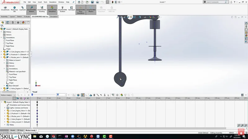
Step 2: Adding Motors for Cam Rotation
The first step in the simulation setup is to rotate the camshaft. For this, we’ll add a motor:
- Click on Motor and select the cam’s axis.
- Set the motor to rotate at 1,200 RPM and click OK.
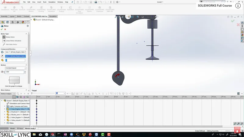
Step 3: Setting Up Contacts
Material contacts are essential for simulating how components interact in real life. Here’s how to define these contacts:
- Go to Contacts and select the first two interacting components, such as the cam and push rod.
- Set material properties to steel-dry for both components.
- Repeat this for the other pairs: push rod and rocker arm, and rocker arm and valve.
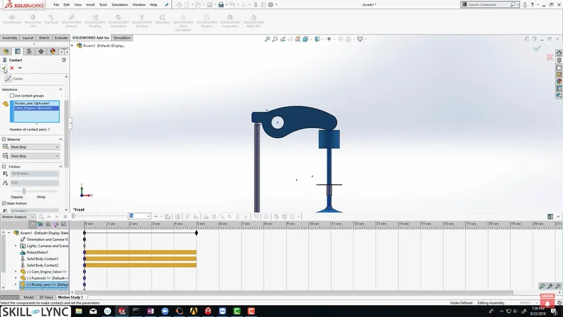
While steel might be the material used for simplicity, real-life materials vary depending on the application. However, using the same material here ensures uniform contact behavior during simulation.
Step 4: Adding a Valve Spring
To simulate the return of the valve, we need to add a spring. Here’s how:
- Click on Spring, select the two edges where the spring will sit.
- Define the free length of the spring to be 35mm and add a pretension by increasing the free length to 45mm. This 10mm pretension ensures the spring remains compressed when the valve is closed, making it realistic.
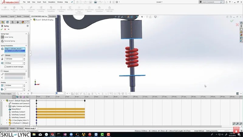
The red color of the spring in the software indicates the pretension, showing the amount of compression.
Step 5: Running the Simulation
- Once everything is set up, we can run the simulation:
- Click Calculate to simulate the cam’s motion and see how it pushes the rocker arm, which then opens the valve.
- Watch how the components interact dynamically, driven by the cam’s rotation and restrained by the spring.
Step 6: Adjusting Output for Crank Angle Data
To get detailed data from the simulation, such as the valve’s linear displacement for each crank angle, adjust the frames per second (FPS) setting:
- The cam rotates at 1,200 RPM, translating to 7,200 degrees per second. So, to capture every crank angle, increase the FPS to 7,200.
- Go to Motion Study Properties and set the FPS to 7,200, ensuring you capture every crank angle for analysis.
Step 7: Checking Material Properties
Make sure the material properties are set correctly:
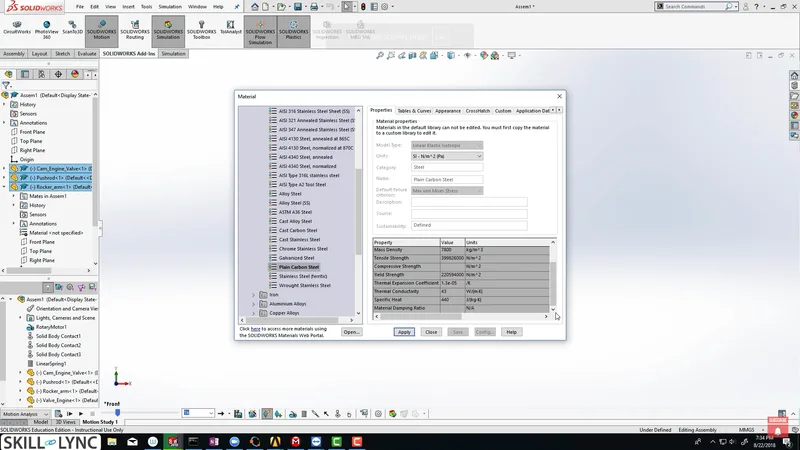
- Right-click on the components, select Edit Material, and choose Plain Carbon Steel. Verify that properties like density, yield strength, and modulus of elasticity are defined.
Step 8: Plotting and Analyzing Results
To analyze how the valve moves during the simulation, plot the linear displacement of the valve:
- Go to Results and Plots, select Linear Displacement, and click on Magnitude.
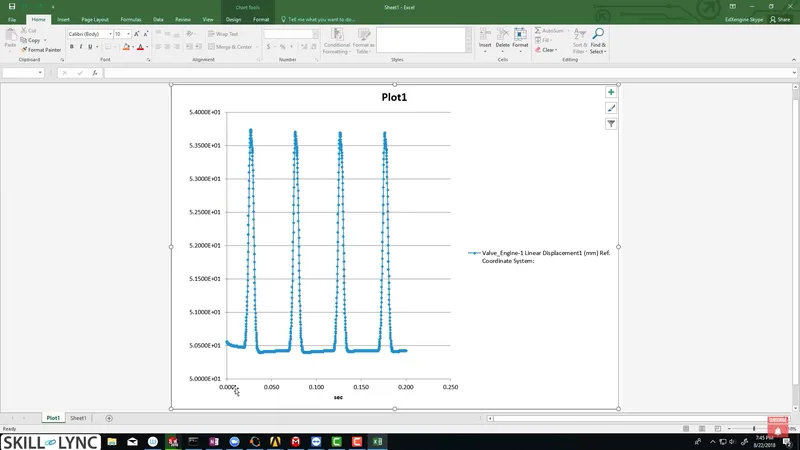
- After selecting the valve component, the plot for the valve lift appears.
- If you notice irregularities in the plot, it could be due to the material or stiffness settings. A key issue could be a low spring stiffness, causing unrealistic motion.
Step 9: Modifying Spring Stiffness
If the spring’s stiffness is too low (for example, 1 Newton/mm), it can cause unstable motion. To fix this:
- Right-click on the spring, select Edit Feature, and change the stiffness to 10 Newton/mm.
Step 10: Exporting Data to Excel
Once the simulation is completed and the plots are generated, you can export the data for further analysis:
- Right-click on the plot and select Export to Spreadsheet.
- This will open Microsoft Excel, allowing you to analyze the data and compare results for different operating conditions.
Conclusion
By following these steps, you’ve successfully simulated and analyzed the dynamics of a valve, cam, and rocker assembly using SolidWorks. Whether you're learning Multibody Dynamics (MBD) using SolidWorks or exploring advanced simulations, this guide provides a comprehensive approach to setting up and refining your motion analysis.
This blog is part of our ongoing series on Multibody Dynamics.
If you missed the previous posts, check them out here.
Would you like to have a more interactive experience going through the SolidWorks user interface?
Skill-Lync has released a FREE comprehensive course covering Multibody Dynamics in detail! Check it out here.
If you’re looking to go deeper into SolidWorks training and multibody dynamics skills, check out Skill-Lync’s SolidWorks certification course.
Check out our hands-on course today and add Multibody Dynamics and SolidWorks to your list of skills!
Let’s get #IndustryReady together, one skill at a time!


