Menu


Modified on
Assembling the Machine Vice in SolidWorks: A Complete Guide

Skill-Lync
Welcome back to the Multibody Dynamics using SolidWorks blog series! In this part of the blog series, we’ll walk through the process of assembling the machine vice with all the components we’ve modeled so far. From inserting components to aligning and mating them, this guide will cover each step to ensure a functional multibody dynamics assembly.
Step 1: Starting the Assembly
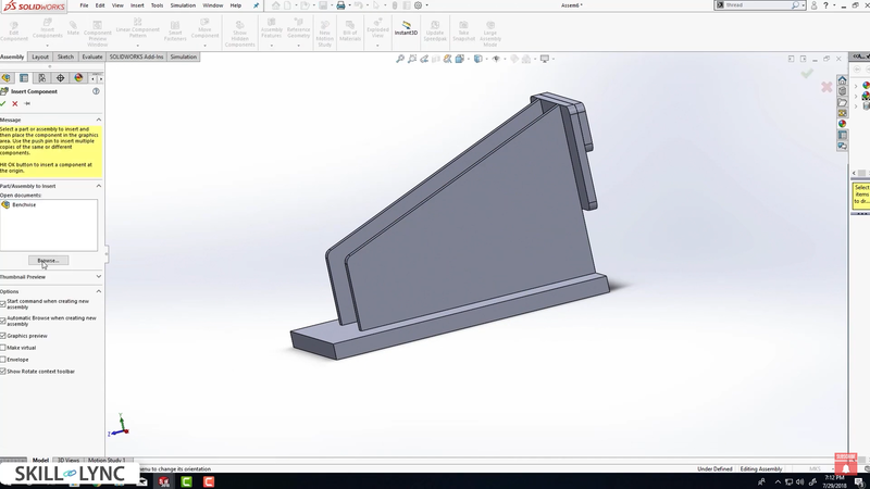
- Open a New Assembly: Go to File > New > Assembly, and click OK. Then, select Browse to load the four components you’ve created. Begin by inserting the bench vise base into the assembly. Since the first part is automatically fixed, try dragging it to see it won’t move. To unfix it, right-click the part and select Float, enabling free movement and rotation.
- Insert Components: Next, go to Assembly > Insert Components and browse to select the screw component. Position the screw relative to the bench vise base. This step ensures the multibody dynamics assembly is correctly set up.
Step 2: Aligning the Components
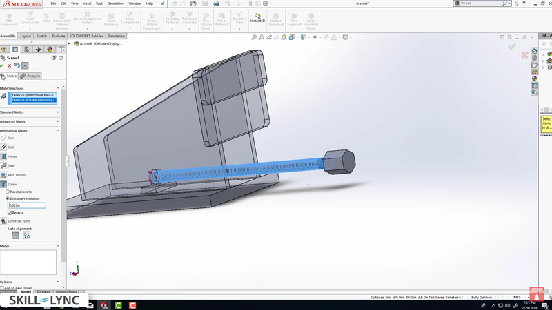
- Mate the Origins: Align the screw with the bench vise base by selecting the origin of the screw and mating it with the assembly origin. You can either use the Mate tool to make the coincident mate or manually align both origins.
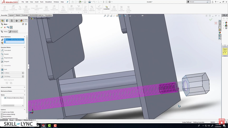
- Inserting the Screw into the Nut: To ensure the screw mates with the nut properly, go to Mechanical Mates, select Screw Mate, and choose the faces of both the screw and nut threads. Adjust the rotation of the screw to ensure it engages perfectly. For example, if you input 360 degrees, the screw rotates one complete revolution. You can also specify a pitch of 25 mm per revolution, ensuring accurate movement.
Step 3: Adding the Slider
- Insert the Slider: After the screw is aligned, insert the slider that will move along with the screw. However, before proceeding, we need to create a hole in the slider for proper assembly.
- Edit the Slider: Right-click the slider and select Open Part. Create a sketch on the front face, use the Circle Tool, and dimension the hole to 9.5 mm in diameter, with the center positioned 21.25 mm from the origin. Once the sketch is completed, perform an Extruded Cut of 5 mm (matching the slider’s thickness). Save and return to the assembly.
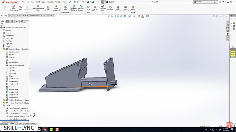
Step 4: Mating the Slider
- Align the Slider: Now, align the slider with the stationary jaw using the Mate tool. Select the inner and outer faces and use a Distance Mate to set an offset of 0.5 mm, ensuring proper alignment in one direction. Repeat the process to ensure alignment on the other axes.
- Fix the Movement: To prevent the slider from moving independently of the screw, apply a coincident mate between the screw and slider faces. This ensures the screw rotation will drive the slider's movement.
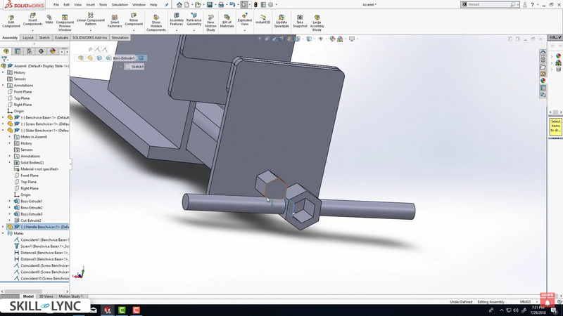
Step 5: Inserting the Handle
- Insert the Handle: Finally, insert the handle component. Select the mating faces and apply coincident mates to align the handle perfectly with the screw.
- Test the Assembly: Rotate the handle to test the functionality of the machine vice. The handle should rotate both clockwise and counterclockwise, causing the screw to rotate and the slider to move accordingly.
Conclusion
You’ve successfully assembled all the components of the machine vice in SolidWorks. This assembly will be crucial for setting up the multibody dynamics simulation in the next stage. By using mechanical mates, aligning parts, and ensuring the slider moves with the screw, your machine vice is now fully functional.
In the next blog, we’ll dive into motion analysis to simulate the movement of this assembly. For more hands-on learning, check out Skill-Lync’s SolidWorks Training, where you can further explore multibody dynamics and SolidWorks simulation techniques.
This blog is part of our ongoing series on Multibody Dynamics.
If you missed the previous posts, check them out here.
Would you like to have a more interactive experience going through the SolidWorks user interface?
Skill-Lync has released a FREE comprehensive course covering Multibody Dynamics in detail! Check it out here.
If you’re looking to go deeper into SolidWorks training and multibody dynamics skills, check out Skill-Lync’s SolidWorks certification course.
Check out our hands-on course today and add Multibody Dynamics and SolidWorks to your list of skills!
Let’s get #IndustryReady together, one skill at a time!
Author
Uma Maheswari K
Author
Skill-Lync
Subscribe to Our Free Newsletter

Continue Reading
Related Blogs
Explore the fundamentals of vehicle dynamics and ultimate trends in the field from design and modeling to control with Skill Lync's exclusive course on the subject. Read about how Skill-Lync's CAE courses can help you get employed.
28 Jul 2020
In this article, we will briefly discuss the working, applications, and features of the one-dimensional systematic simulation tool, GT-Power, in Emission Control Strategy, engine calibration, hybrid vehicle modeling. Read about how Skill-Lync's CAE courses can help you get employed.
28 Jul 2020
This article offers a brief introduction to the globally accepted standard of Geometric Dimensioning and Tolerancing, and its importance for the entire manufacturing process. Read about how Skill-Lync's CAE courses can help you get employed.
28 Jul 2020
In this blog we will read about Going a step into Biomechanics and how Skill-Lync's CAE course will help you get employed.
09 May 2020
The powertrain is the most prominent source of vibrations that affects the driving experience for the people on board. This blog from Skill-Lync examines these vibrations to help enhance that experience.
21 Aug 2020
Author
Skill-Lync
Subscribe to Our Free Newsletter
Continue Reading
Related Blogs
Explore the fundamentals of vehicle dynamics and ultimate trends in the field from design and modeling to control with Skill Lync's exclusive course on the subject. Read about how Skill-Lync's CAE courses can help you get employed.
28 Jul 2020
In this article, we will briefly discuss the working, applications, and features of the one-dimensional systematic simulation tool, GT-Power, in Emission Control Strategy, engine calibration, hybrid vehicle modeling. Read about how Skill-Lync's CAE courses can help you get employed.
28 Jul 2020
This article offers a brief introduction to the globally accepted standard of Geometric Dimensioning and Tolerancing, and its importance for the entire manufacturing process. Read about how Skill-Lync's CAE courses can help you get employed.
28 Jul 2020
In this blog we will read about Going a step into Biomechanics and how Skill-Lync's CAE course will help you get employed.
09 May 2020
The powertrain is the most prominent source of vibrations that affects the driving experience for the people on board. This blog from Skill-Lync examines these vibrations to help enhance that experience.
21 Aug 2020
Related Courses


