Drafting in Solidworks
Learn the essentials of drafting in SolidWorks, including setting sheet formats, selecting standard views, adding dimensions, and creating annotations. This guide covers custom drawing templates, sectional views, BOM integration, and detailed views to streamline your design process.
Solidworks allows us to select a sheet format. The sheet format controls:
- Size of the drawing sheet
- Drawing borders
- Title block
- Sheet scale
We can create custom drawing templates with any of the following characteristics:
- Drawing sheet size (fA0, A1, A3, …)
- Drawing standard (for example, ISO and ANSI…)
- Units (for example, millimeters and inches…)
1. Click on File> new> Drawing
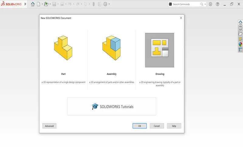
2.Select the sheet of required size and also sizes can be customized in custom size 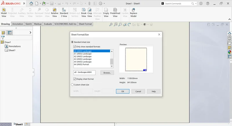
3. Select model view and browse for required file
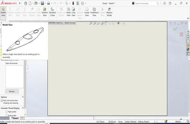
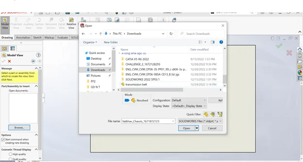
5. After browsing the selected views can be selected and also scaling can be customized.
Drawing Views
Drawing views are placed on drawing sheets and contain the images of the parts or assemblies, plus dimensions and annotations.
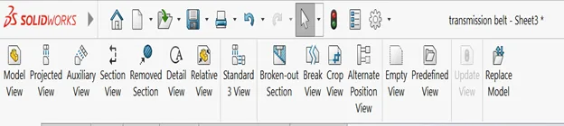
Drawings begin with standard views. From those views, we can derive other types of views, such as projected, section, and detail.
Standard 3 Views
Standard 3 views, as the name implies, comprise three views: front, top, and right (third angle projection) or front, top, and left (first angle projection).
Next We add an isometric view of the cabinet (a named view) to the drawing sheet.
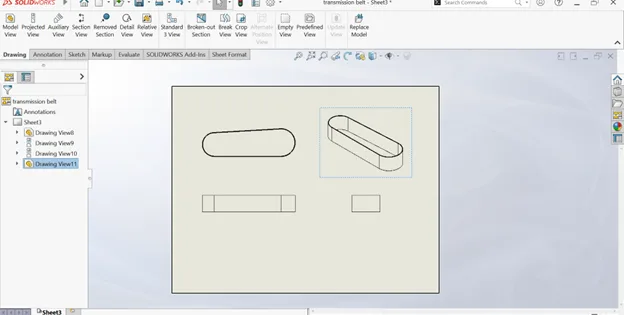
Different views can be also attached into the sheet
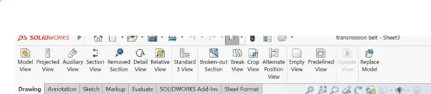
Dimensions
In a SOLIDWORKS drawing are associated with the model. Changes in the model are reflected in the drawing, and vice versa.we can also add dimensions in the drawing document, but these are reference dimensions, and are driven; we cannot edit the value of reference dimensions to change the model. The values of reference dimensions change when the model dimensions change. We can set the units (ex, millimeters or inches) and the drawing standard ( ex ISO or ANSI) in the detailing options.
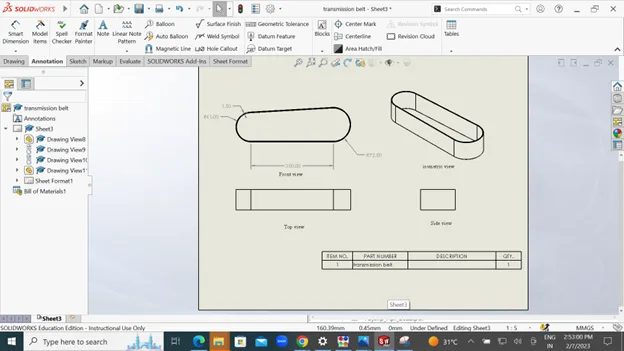
Dimensioning can be provided using smart dimensions
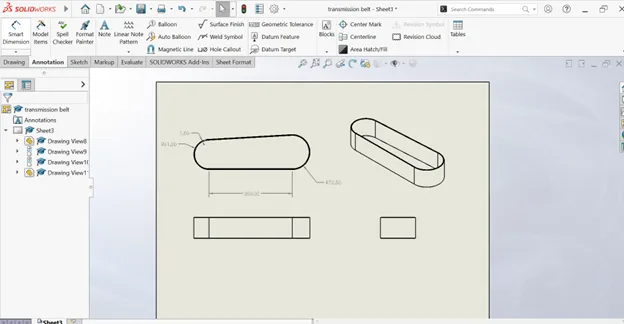
Annotations
In addition to dimensions, we can introduce annotations to our models and drawings to convey manufacturing information:
- Notes
- Geometric tolerance symbols
- Datum feature symbol
- Center marks
- Surface finish symbols
- Datum target symbols
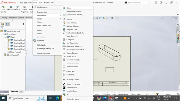
Annotations
Different annotations can be inserted in following way

Bill of Materials
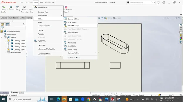
BOM can be inserted
Sectional Views
We can create a section view in a drawing by cutting the parent view with a section line. A section view of the faucet in the faucet assembly drawing shows the faucet pipe walls and connections.
Detailed Views
Detailed views show a portion of an orthographic, 3D, or section view at an enlarged scale. The connection of the faucet is shown in a detail view. The parent view is the section view.
With these, the solidworks drafting is complete with dimensions.


