Understanding Leader and Multi-Leader Commands in AutoCAD: A Comprehensive Guide
Master the Leader and Multi-Leader commands in AutoCAD for precise annotations in AutoCAD 2D and 3D drawings. Enhance clarity and professionalism in your technical drawings, perfect for engineers and beginners alike.

Welcome back to the AutoCAD Essentials for Mechanical Engineers series! In this part of the blog series, we’ll dive deep into the Leader and Multi-Leader commands. These annotation tools are essential for providing clarity in your technical drawings by adding reference text or notes connected to specific points in your design. Whether you're dealing with radius dimensions, tolerances, or multi-line annotations, mastering these commands will significantly enhance the precision and professionalism of your AutoCAD drawings.
What is a Leader in AutoCAD?
A leader in AutoCAD refers to an annotation tool used to extend a reference line from a particular feature or point and add explanatory text, dimensions, or symbols to a drawing. This command is often used to label holes, diameters, or specific dimensions. The leader line typically consists of an arrowhead pointing to the object with a horizontal or angled line leading to the annotation.
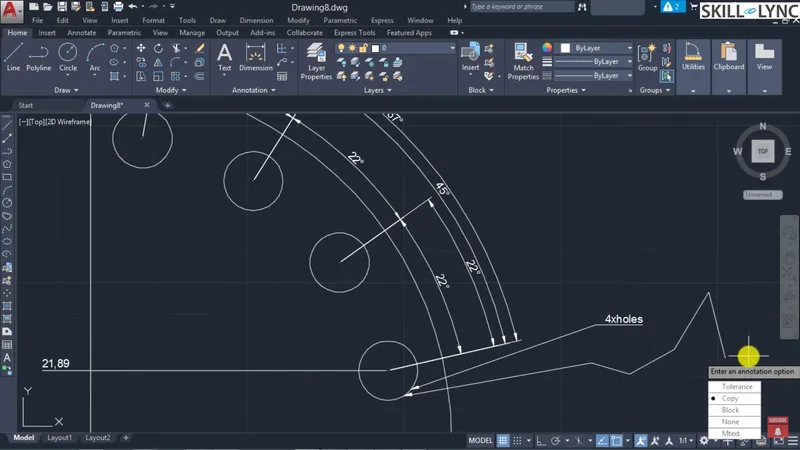
Example: Annotating Hole Specifications
Let's say you want to specify that four holes, each with a diameter of 10 mm, are positioned along a circular pattern. This information can be annotated using the Leader command, linking the annotation to the circle's reference point.
To invoke the leader, simply type the command LEADER or select the leader tool. You can then define the start point of the leader (e.g., a hole) and add the annotation text (e.g., "4X Ø10 mm"). The Leader tool is highly customizable, allowing you to choose between different arrow styles, line types, and annotation formats.
Step-by-Step Guide to Using the Leader Command
Invoke the Leader Command: Use the LEADER command.
- Specify the Start Point: Select the object or feature you want to annotate.
- Create the Leader Line: Drag and place the annotation at the desired location. You can add multiple leader points for more complex annotations.
- Add Text: AutoCAD will prompt you to add annotation text, such as "4X Ø10 mm". You can adjust the formatting (font, size, justification) as needed.
- Finalize the Leader: After placing the annotation, AutoCAD automatically generates the leader with an arrow and annotation box.
Using Q Leader for Quick Annotations
For faster annotations, Q Leader is a simplified version of the leader command, ideal for repetitive tasks where the same annotation is used multiple times. You can pre-define the annotation and format, which allows for quick insertion without manually typing each time.
Steps:
Invoke the Q Leader Command (QLEADER).
- Set the Leader Point: Select the point on the object.
- Predefined Annotation: The annotation text is already predefined, making it easier for consistent, repetitive annotations.
- Multi-Leader: Adding Multiple Annotations with a Single Command
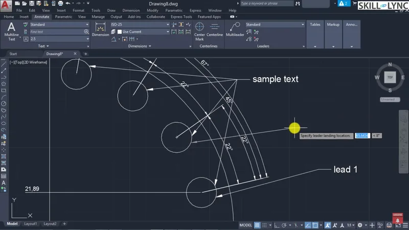
In more complex drawings, you may need to reference the same annotation for multiple features. This is where the Multi-Leader command (invoked by MLEADER) becomes valuable. It allows you to attach multiple leaders to a single annotation, making your drawing cleaner and more organized.
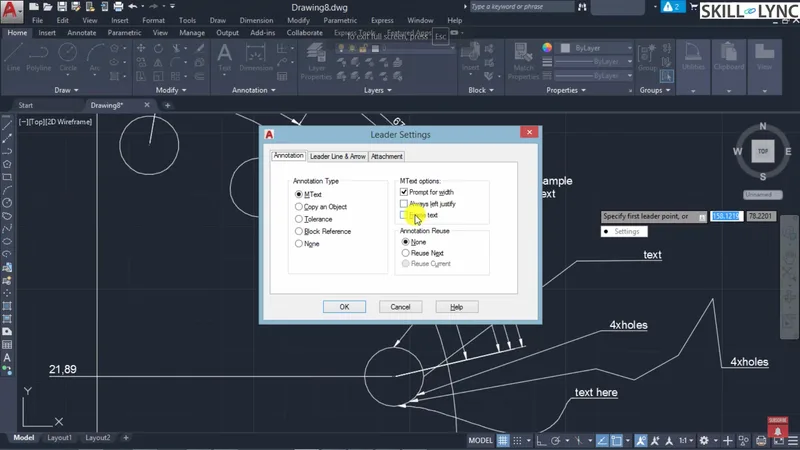
How to Use Multi-Leader:
- Invoke the Multi-Leader Command: Type MLEADER.
- Select the Arrowhead Position: Choose the points on the drawing where the leader lines will attach.
- Place the Annotation: Add the common text or dimensions.
- Add Additional Leader Lines: You can add more leader lines by selecting the same annotation and specifying new attachment points.
This feature is particularly useful when the same annotation applies to multiple objects, such as identifying a material type or labeling dimensions for repeated features.
Customizing Leaders and Multi-Leaders
AutoCAD provides extensive customization options for both leader and multi-leader commands. In the Leader Settings menu, you can modify:
- Line Types: Choose between straight or spline leader lines.
- Arrowheads: Select different arrowhead styles, such as closed, open, or none.
- Text Format: Customize the annotation’s font, size, and placement.
For Multi-Leaders, you can define the number of leader lines, alignment, spacing between leaders, and angle constraints. For example, you can maintain a consistent 30° or 45° angle between leader lines to follow standard dimensioning practices in AutoCAD mechanical engineering.
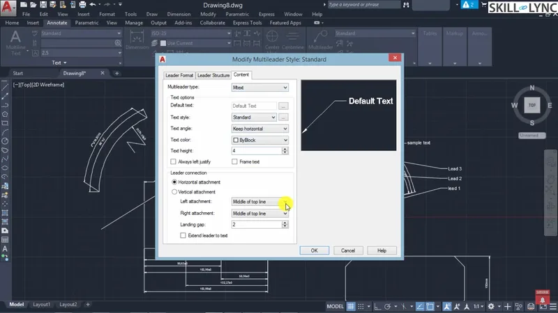
Aligning and Spacing Leaders for Better Readability
In some drawings, leaders may overlap or become cluttered, especially in dense technical drawings. To ensure readability:
- Use the Align Command (MLEADERALIGN): Align multiple leaders so that their text is neatly spaced and parallel.
- Control Leader Spacing: Set specific spacing between leader lines to avoid overlap and make the drawing more legible.
For example, if you have multiple leader annotations and want them evenly spaced at 8 mm intervals, use the alignment tool to distribute them accordingly.
Associative Dimensions: A Smart Way to Maintain Accuracy
One of the advanced features in AutoCAD is Associative Dimensions. This allows dimensions and annotations to automatically update when the object they reference is scaled or modified. This is particularly useful in AutoCAD 3D or large mechanical designs, where objects may be resized or repositioned.
To enable associative dimensions:
- Set the Associative Dimension Property: Make sure the system variable for dimension associativity (DIMASSOC) is set to 2 (Associative).
- Create the Dimension: As you scale or move objects, the dimensions update automatically, maintaining their relative accuracy.
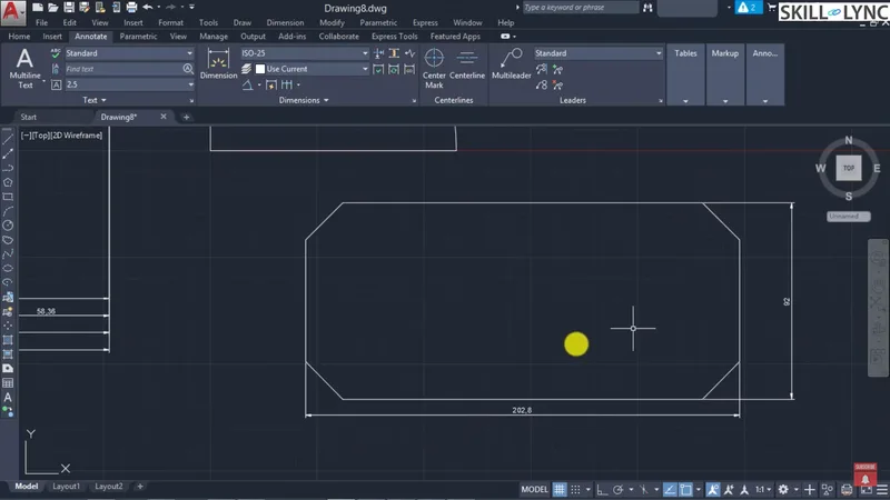
There are instances when you need to edit or modify dimension text or styles. The Dimension Edit command (DIMEDIT) allows you to:
- Move Text: Reposition dimension text for better visibility.
- Rotate Text: Adjust the angle of the dimension text.
- Oblique Extension Lines: Change the angle of extension lines to avoid conflicts with other drawing features.
By modifying these dimension properties, you can improve the clarity and precision of your drawings.
Conclusion: Master Leader and Multi-Leader Commands for Better AutoCAD Drawings
Leaders and multi-leaders are essential for creating clear, detailed AutoCAD mechanical drawings. Whether you're working on AutoCAD 2D for beginners or advanced AutoCAD 3D models, knowing how to annotate with leaders will elevate the quality of your work. These tools help engineers communicate complex details effectively, whether for manufacturing, inspection, or assembly.
By mastering commands like Q Leader, Multi-Leader, and Associative Dimensions, you’ll not only save time but also ensure that your drawings are professional and accurate.
This blog is part of our ongoing AutoCAD Design Series. If you missed the previous posts, check them out here.
Would you like to have a more interactive experience going through the AutoCAD essentials?
Skill-Lync has released a FREE comprehensive course covering AutoCAD Essentials for Mechanical Engineers in detail! Check it out here.
If you’re looking to go deeper into AutoCAD Essentials check out Skill-Lync’s AutoCAD certification course.
Check out our hands-on course today and add AutoCAD to your list of skills!
Let’s get #IndustryReady together, one skill at a time!


