Tolerancing in AutoCAD for Mechanical Engineers: An Essential Guide
Tolerancing in AutoCAD is crucial for mechanical engineers to ensure precise fit and functionality. This guide covers key tolerancing techniques in AutoCAD 2D and AutoCAD 3D, including types of tolerances, allowances, datums, and fits, all essential for creating high-quality, reliable designs.

Welcome back to the AutoCAD Essentials for Mechanical Engineers series! In the world of mechanical engineering, precision is more than a preference—it’s an absolute necessity. Every component, no matter how small, needs to fit and function seamlessly within larger assemblies. This is where tolerancing becomes essential.
By defining acceptable limits for dimensional and geometrical variations, tolerancing ensures that each part produced meets strict design requirements, functions reliably, and fits into assemblies without any issues. In this week’s continuation of the AutoCAD Essentials for Mechanical Engineers series, we’ll dive into tolerancing techniques using AutoCAD 2D and AutoCAD 3D tools. With these insights, you’ll learn how to create high-quality, functional designs that stay true to their intended performance from production through inspection.
Let’s explore how tolerances make all the difference in AutoCAD for mechanical engineers, helping to achieve precision, reduce costs, and ensure every part performs exactly as expected.
Understanding Tolerancing in AutoCAD
Imagine comparing an original Vincent van Gogh painting with a mass-produced Logitech mouse. The artwork is unique, while the mouse is one among millions. The challenge with mass production is ensuring that each item functions as expected, even with slight variances. This is where tolerancing comes in, as it allows for some level of variation while ensuring the component remains interchangeable and functional.

Why Is Tolerancing Important?
No component is perfectly manufactured; slight variances will always exist due to limitations in manufacturing capability, inspection quality, and measurement precision. Setting tolerances allows these variations within acceptable limits, ensuring components can be easily replaced without impacting the entire assembly. This approach is critical in maintaining standardization and interchangeability of parts across applications, keeping inventory variations to a minimum and supporting mass production.
In short, tolerancing defines acceptable dimensional and geometrical variances to make sure a part:
- Meets functional requirements.
- Is compatible with assembly processes.
- Can be reliably inspected and verified.
Types of Tolerances and Their Application
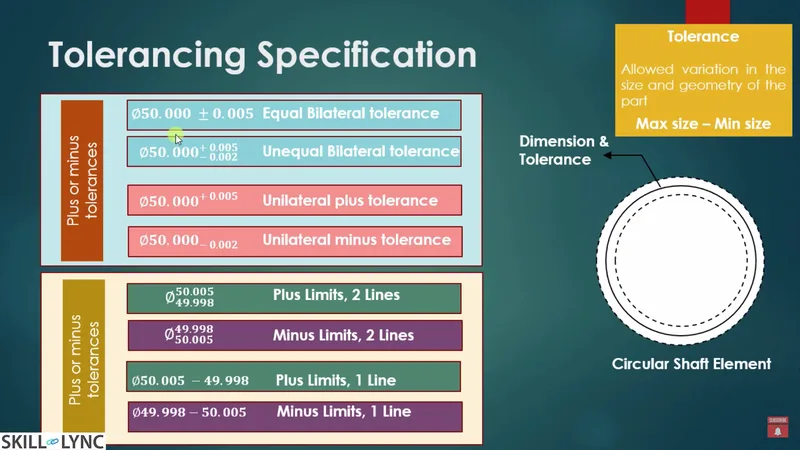
When defining tolerances, we focus on the permissible range between maximum and minimum dimensions. Here are the main types of tolerances used in AutoCAD for mechanical engineers:
- Bilateral Tolerance: Variance is allowed in both directions. For instance, a 50mm diameter shaft with a ±0.5mm tolerance has a range of 49.5 to 50.5mm. This can be an equal bilateral tolerance (±0.5mm) or an unequal bilateral tolerance (e.g., +0.5/-0.2mm).
- Unilateral Tolerance: Variance is permitted in only one direction. For instance, a shaft dimension of 50mm might allow a +0.5mm tolerance only, setting a range from 50mm to 50.5mm.
- Limit Dimensions: Here, we set exact upper and lower bounds. For example, a shaft dimension might be given as 50.5mm upper limit and 49.8mm lower limit.
These tolerancing methods are foundational in AutoCAD drawing for achieving precise mechanical design.
Key Terminologies in Tolerancing
Understanding tolerancing in CAD programs involves several key concepts:
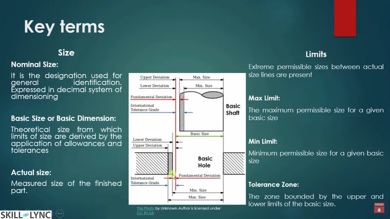
- Nominal Size: The identification used to refer to a part. For instance, a 50mm shaft is referred to as a 50mm nominal size.
- Basic Size: The theoretical value from which limits are applied to achieve the necessary allowances.
- Actual Size: This is the size of the component once manufactured, after all production processes are complete.
- Maximum and Minimum Limits: These define the extremes permissible. For example, for a shaft with a 50mm nominal size and a tolerance of ±0.5mm, the maximum limit is 50.5mm, and the minimum limit is 49.5mm.
- Deviation: This is the difference between the basic and actual sizes, determining whether the actual part is within permissible limits.
Using Datums for Reference in Tolerancing
Datums are critical in AutoCAD essentials. They provide a reference point or line from which to measure component variations, ensuring consistent inspection processes. Derived from features such as planes or axes, datums are completely theoretical and used solely for reference.
When setting up datums:
- Primary Datum: Establishes the main reference plane.
- Secondary and Tertiary Datums: Provide additional reference planes at right angles to the primary datum.
These references, often defined within the datum reference frame in AutoCAD 2024, ensure components are measured accurately, maintaining alignment with 3D CAD standards.
Allowances and Clearances: Essential for Assembly Fits
Allowance and clearance are terms essential to defining the interaction between mating parts in AutoCAD for mechanical engineers.
- Allowance: The minimum intended difference between the hole and shaft sizes in a fit, determining how snugly they fit together. A positive allowance means a clearance fit, while a negative allowance indicates an interference fit.
- Clearance: The maximum difference between mating parts, ensuring no interference.
Based on allowances and clearances, fits are classified as:
- Clearance Fit: Parts fit with a small gap, allowing for free movement.
- Transition Fit: Parts may be snug or require slight force to fit.
- Interference Fit: Parts require significant force to fit together, ensuring no relative movement between them.
In AutoCAD online courses, understanding these fits is crucial for determining whether to use hole-basis or shaft-basis systems for assembly.
Representing Tolerances in AutoCAD Drawings
In AutoCAD mechanical engineering, tolerances are often represented using symbols to convey essential information concisely. In AutoCAD training programs, students learn how to denote fits and tolerances effectively to communicate design intent clearly.
For instance:
- Hole Basis System: The hole dimension is constant, while the shaft’s dimensions vary.
- Shaft Basis System: The shaft dimension is constant, while the hole’s dimensions vary.
Using GD&T (Geometric Dimensioning and Tolerancing) symbols in AutoCAD mechanical drawing helps in specifying the necessary tolerances for manufacturing and inspection.
Conclusion
As we explore tolerancing in AutoCAD for engineers, it’s clear that these techniques are essential for ensuring precision, functionality, and interchangeability. From defining size limits and deviations to understanding the role of datums and allowances, these methods ensure our designs are both manufacturable and inspectable.
For those interested in mastering tolerancing, many AutoCAD courses for beginners and AutoCAD certification programs offer in-depth lessons on this topic. Remember, applying these concepts will elevate your proficiency in AutoCAD essentials and improve the quality of your designs.
In our next session, we will look further into Geometric Dimensioning & Tolerancing (GD&T) applications within AutoCAD 3D crash courses. Stay tuned, and keep exploring the limitless possibilities with top CAD software for mechanical engineers.
This blog is part of our ongoing AutoCAD Design Series. If you missed the previous posts, check them out here.
Would you like to have a more interactive experience going through the AutoCAD essentials?
Skill-Lync has released a FREE comprehensive course covering AutoCAD Essentials for Mechanical Engineers in detail! Check it out here.
If you’re looking to go deeper into AutoCAD Essentials check out Skill-Lync’s AutoCAD certification course.
Check out our hands-on course today and add AutoCAD to your list of skills!
Let’s get #IndustryReady together, one skill at a time!


