Mastering Fit and Tolerance Grades in AutoCAD for Mechanical Engineering
Master fit and tolerance in AutoCAD to enhance the precision and reliability of mechanical designs. Explore fit types, tolerance grades, and essential GD&T symbols to ensure accurate, functional, and cost-effective AutoCAD 2D and AutoCAD 3D drawings, foundational for engineers in CAD programs and mechanical AutoCAD applications.
Welcome back to another blog in our AutoCAD Essentials for Mechanical Engineers series! This blog, we’ll delve deeper into the critical aspects of fit and tolerance, essential components in mechanical design to ensure product functionality, reliability, and consistency in manufacturing. Whether you’re creating an AutoCAD 2D drawing for beginners or diving into AutoCAD 3D designs, mastering fit and tolerance standards will be invaluable.
Exploring Fit Types in Mechanical Assemblies
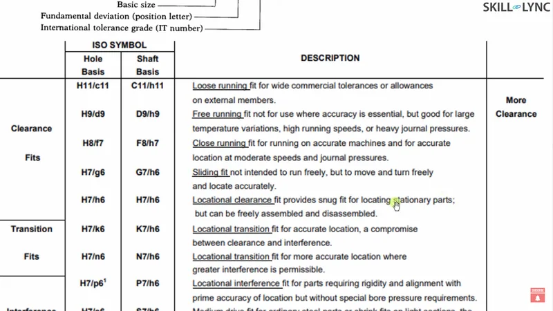
In the first step, let’s look at the basics of fits—specifically in a hole basis system where we focus on the hole size as our base measurement.
- Loose Running Fit (H1 and C1): This combination is often used for parts where components have no interaction. It’s ideal for assemblies where components can slide or fit loosely without affecting the final outcome—think of it as a commercial tolerance setup used for items like external machine parts that don’t require high precision.
- Free Running Fit: Designed for applications requiring accuracy, especially in environments with high temperatures, high-speed rotation, or significant pressure. This fit type is essential in conditions where AutoCAD mechanical drawings demand smooth running, such as in high-speed rotors or shafts.
- Close Running Fit: Necessary for high-precision components, this fit is used in assemblies requiring moderate speeds and pressures. The close running fit provides an accurate alignment, crucial in mechanical engineering components where precision ensures reliable functionality.
- Sliding Fit: Not designed for free-running, sliding fits work well for parts that need controlled movement with accurate positioning. This is often used in stationary assemblies or snug-fit applications, where positioning is critical.
- Transition and Interference Fits: Transition fits cover both clearance and interference zones, providing a balanced fit with controlled alignment. Interference fits require greater force for assembly, often needing heating or cooling of parts to secure them tightly together. This fit type is common in gear assemblies and wheel hubs.
Grades of Tolerances: Defining Manufacturing Precision
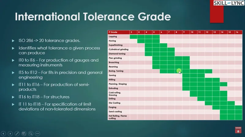
Tolerance grades are defined by ISO 286, outlining 20 grades used to specify the acceptable tolerance levels based on the manufacturing process:
- Tighter Grades (IT0 to IT6): These tolerance grades are used for high-precision components, like gauges and measurement instruments. They’re essential for measuring variations accurately, keeping tolerances as close to ideal as possible.
- Intermediate Grades (IT5 to IT12): Commonly applied in general engineering processes, these grades are suitable for parts requiring standard tolerances.
- Semi-Product Grades (IT11 to IT16): These grades are often used for semi-finished products that still require additional machining before the final assembly.
- Higher Tolerance Grades (IT16 to IT18): These are used in civil engineering applications and other fields where large tolerance ranges are permissible.
Understanding and applying these grades in AutoCAD for mechanical engineers is essential for accurate designs, especially when transitioning from 2D CAD software to 3D CAD programs.
Calculating Tolerance Grades
Tolerance grades help define the maximum deviation allowed for a part, and it’s essential to understand how these tolerances are calculated. Here’s the formula for tolerance calculation:
T=10I2×(45×D1/3+0.1×D)T = 10^{\frac{I}{2}} \times (45 \times D^{1/3} + 0.1 \times D)T=102I ×(45×D1/3+0.1×D)
Where:
T = Tolerance in micrometers
D = Nominal diameter in millimeters
I = Tolerance grade index
For instance, in AutoCAD essentials training or an AutoCAD mechanical crash course, this formula becomes highly relevant as students explore tolerance implications in practical applications.
Tolerance Zones and Symbolism in AutoCAD
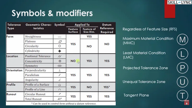
Symbols and modifiers in GD&T (Geometric Dimensioning and Tolerancing) visually communicate tolerance specifications. Each symbol defines an aspect of tolerance and its application to a part’s design:
- Form Tolerances: These control the shape of a part. Examples include:
- Straightness: Ensures a line remains within two parallel planes.
- Flatness: Controls that a surface stays within two parallel planes.
- Circularity and Cylindricity: For round and cylindrical surfaces, these tolerances control form deviation within defined tolerance zones.
- Location Tolerances: Indicate the precise positioning, such as position (true position) and concentricity.
- Orientation Tolerances: Control angular relationships. These include perpendicularity, parallelism, and angularity.
Understanding these tolerances and symbols in AutoCAD training is essential for clear communication between designers and manufacturers, ensuring the part will meet functional and quality requirements in a 3D CAD environment.
Applying GD&T in AutoCAD: Essential for Mechanical Engineers
Incorporating GD&T symbols and tolerance grades in AutoCAD for engineers is vital for quality, functionality, and interchangeability of parts. These techniques allow engineers to convey precise requirements for AutoCAD 2D and 3D drawings, from beginner CAD tutorials to advanced levels, ensuring that every specification aligns with industry standards.
Using tolerance grades and GD&T symbols, engineers can control the exact manufacturing specifications for components, ensuring precision without incurring unnecessary costs. This knowledge forms the foundation of expertise for anyone pursuing an AutoCAD mechanical engineering course or a CAD tutorial.
Conclusion
Understanding the fit types, tolerance grades, and GD&T symbols is essential for creating high-quality AutoCAD mechanical drawings. By mastering these elements, mechanical engineers can ensure their designs are accurate, functional, and cost-effective, adhering to standards across CAD programs and design software for mechanical engineers.
This blog only scratches the surface. For those looking to dive deeper, our AutoCAD essentials training provides hands-on applications and in-depth knowledge to help you master these critical skills in AutoCAD for beginners and experienced users alike.
This blog is part of our ongoing AutoCAD Design Series. If you missed the previous posts, check them out here.
Would you like to have a more interactive experience going through the AutoCAD essentials?
Skill-Lync has released a FREE comprehensive course covering AutoCAD Essentials for Mechanical Engineers in detail! Check it out here.
If you’re looking to go deeper into AutoCAD Essentials check out Skill-Lync’s AutoCAD certification course.
Check out our hands-on course today and add AutoCAD to your list of skills!
Let’s get #IndustryReady together, one skill at a time!


