Mastering Blocks in AutoCAD
Discover the power of blocks in AutoCAD to streamline your mechanical drawings! Learn how blocks can save time, maintain consistency, and simplify complex designs in this essential guide for engineers

Welcome back to AutoCAD Essentials for Mechanical Engineers blog series. In this blog, we're exploring one of AutoCAD’s most powerful tools: blocks. The use of blocks in AutoCAD mechanical drawings can save hours of work, streamline repetitive tasks, and ensure consistent quality across all of your designs. This is a key skill for any engineer using CAD software, so let's dive in!
Understanding Blocks in AutoCAD
A block in AutoCAD is a collection of objects grouped to form a single entity. Imagine a hexagonal nut or a bolt—these components have standard dimensions, and each version varies only slightly based on specifics such as major diameter or pitch. With blocks, you can create a standard component and insert it wherever needed in your AutoCAD drawing, scaling, rotating, or exploding it to suit your needs. This not only saves time but also allows for modifications across all instances of the block in a drawing, maintaining consistency.
Key Benefits of Blocks:
- Efficiency: Insert a saved block instead of creating a new one each time, reducing repetitive work.
- Standardization: Build a library of frequently used symbols and components, ensuring quality and uniformity.
- File Management: Store all references to the same block as a single entity, reducing file size.
- Flexibility: Scale, rotate, and modify each instance as needed.
Creating a Block: Step-by-Step Guide
Let’s walk through the creation of a block using a hexagonal nut as an example, a standard component in mechanical AutoCAD.
1. Define the Geometry
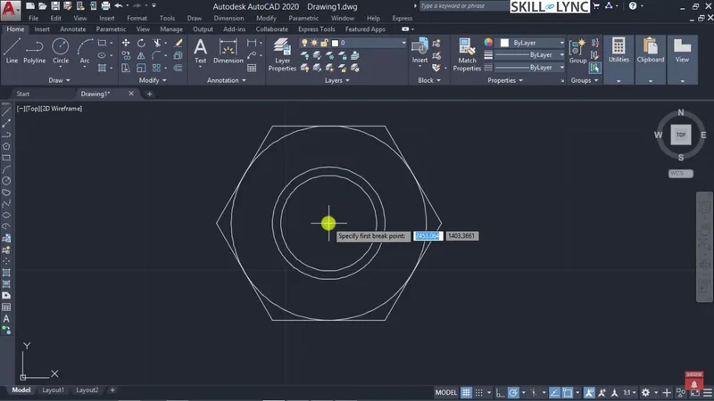
- To create a hexagonal nut, start by drawing a hexagon.
- Use the polygon tool with 6 sides and center it within a circle.
- Assign dimensions to the radius (for example, 8 mm for the internal threaded hole).
- Add chamfered edges to reflect the real appearance of a hex nut in top view.
2. Create Internal Threads
Next, add the threaded hole by creating an inner circle with a diameter of 6.8 mm, representing the internal thread. Use the Break command to separate sections as needed for accurate representation.
3. Save as a Block
To save this component as a block:
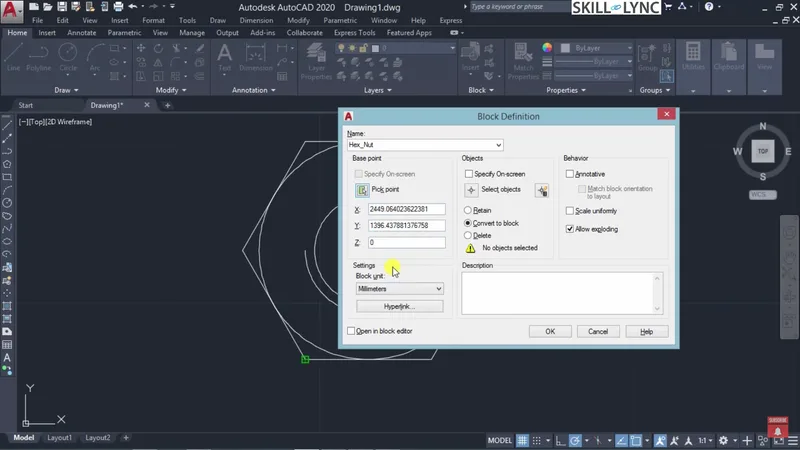
- Open the Block Definition dialog box by using the command BLOCK.
- Name the block, for example, "HexNut."
- Specify a base point, which will serve as the insertion point for each instance.
- Select all elements of the hex nut as objects for the block.
You can also use the Quick Select feature to capture all related elements. Once selected, define how you want to handle the original component by choosing to retain, convert to block, or delete the initial elements.
4. Set Block Attributes and Behaviors
In the Block Definition dialog box, you’ll find options to set up block attributes and behaviors:
- Annotative: Aligns the block with the layout orientation in paper space.
- Uniform Scaling: Ensures the block scales consistently across all directions.
- Explode Option: Allows you to break the block into its individual elements if needed.
Add a description to the block (e.g., “HexNut, major diameter 8 mm”) for easy reference.
Inserting Blocks with Dynamic Input
Once your block is saved, you can insert it into your drawing in various ways:
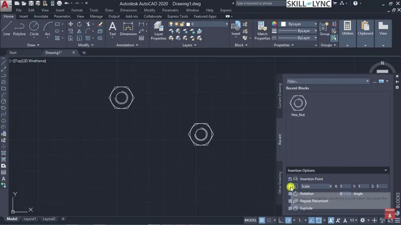
- Direct Insert: From the Home ribbon, select Insert Block or use the INSERT command. You can adjust scale, rotation, and position dynamically using Dynamic Input.
- Rotation and Scaling: Adjust the scaling in the x, y, and z directions or specify a rotation angle.
- Repeat Placement: Place multiple copies in one action, saving even more time.
- Explode: Break down the block into its original components for modification.
Writing Blocks to Files (WBlock)
With the WBlock (Write Block) command, you can save blocks as standalone files, making them accessible in other projects. This tool is useful for sharing standard parts like bolts or nuts across teams or projects.
To use WBlock:
- Select your source block or specific elements.
- Save as an AutoCAD file (.dwg).
- Choose a location, and now your block is accessible in other AutoCAD 2024 projects.
Block Attributes and Base Points
Block attributes allow you to embed metadata like part numbers or material types within the block, which can be synchronized across the entire drawing. Setting a base point makes it easier to position the block consistently in each new location.
Constraints and Dynamic Blocks
Constraints provide further control over block behavior. Geometric constraints ensure that components within a block maintain their relative positions. For instance, in a hex nut, we can constrain the inner circle to be concentric with the outer hexagon.
1. Geometric Constraints:
- Concentric: Keeps two circles aligned at the center.
- Tangency: Ensures lines are tangent to circles.
- Fixed: Locks a component in place to avoid accidental movement.
Wrapping Up: Why Blocks Matter in Mechanical Engineering Drawings
Using blocks is essential in AutoCAD for mechanical engineers, as it enhances productivity, quality, and consistency across projects. AutoCAD training often emphasizes mastering blocks as a foundational skill, as it saves time and memory in complex projects. With CAD software like AutoCAD, blocks become part of your toolbox for efficient, professional designs.
Whether you’re exploring AutoCAD 2D or AutoCAD 3D, understanding blocks and their behaviors is crucial for managing designs effectively. As you continue through this AutoCAD Essentials series, integrating blocks into your skill set will elevate your expertise, helping you create streamlined, standards-compliant AutoCAD mechanical engineering drawings.
This blog is part of our ongoing AutoCAD Design Series. If you missed the previous posts, check them out here.
Would you like to have a more interactive experience going through the AutoCAD essentials?
Skill-Lync has released a FREE comprehensive course covering AutoCAD Essentials for Mechanical Engineers in detail! Check it out here.
If you’re looking to go deeper into AutoCAD Essentials check out Skill-Lync’s AutoCAD certification course.
Check out our hands-on course today and add AutoCAD to your list of skills!
Let’s get #IndustryReady together, one skill at a time!


