Mastering AutoCAD Dimensioning: A Guide for Mechanical Engineers
Master AutoCAD dimensioning with essential tools for mechanical engineers. Learn to apply linear, angular, radius, and advanced dimensioning techniques in AutoCAD 2D and 3D for accurate, manufacturable designs.
Welcome back to the AutoCAD Essentials for Mechanical Engineers series! In this blog, we are diving into the crucial topic of dimensioning. Proper dimensioning is vital for clear communication in technical drawings, ensuring that your design can be accurately interpreted and manufactured. Whether you are working on AutoCAD 2D, AutoCAD 3D, or specializing in mechanical AutoCAD, this guide will help you understand the available dimensioning tools and how to use them effectively.
Dimensioning Tools in AutoCAD
AutoCAD offers a wide range of dimensioning tools that are accessible through both the Dimension menu and the Annotate tab. Here's a breakdown of the different dimensions available:
- Quick Dimension
- Linear Dimension
- Aligned, Arc Length, and Ordinate Dimensions
- Angular, Jog, Diameter, and Radius Dimensions
- Oblique Dimensions
- Multileader Dimensioning
- Tolerances and Center Marks
- Inspection Dimensions
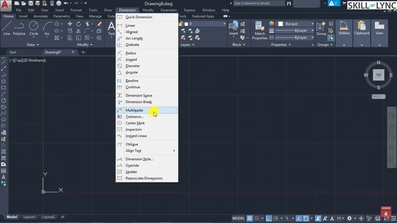
These tools can also be accessed in the Home tab under the annotation section, making it easy to dimension your drawings. This is particularly useful for engineers learning AutoCAD for beginners or taking an AutoCAD free certification course.
Linear Dimensions in AutoCAD
Let’s begin by looking at linear dimensions, one of the most common types used in AutoCAD 2D drawings for mechanical engineers. There are two methods for specifying a linear dimension:
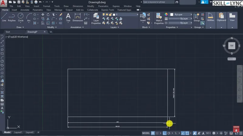
- Specifying Origin Points: This method involves picking two points on the object to define the dimension. For example, when drawing a rectangle, you can specify the first point and then the second point of the extension line, followed by selecting the position of the dimension text. This method allows you to control the alignment and position of the dimension.
- Selecting the Object Directly: The second method allows you to select an object directly, and AutoCAD automatically assigns the dimensions. This is a faster way to dimension when working with pre-drawn objects like rectangles, circles, or other shapes in your AutoCAD mechanical drawing.
Both methods are essential for AutoCAD mechanical engineers, as they simplify the process of dimensioning critical parts and assemblies.
Customizing Dimension Text
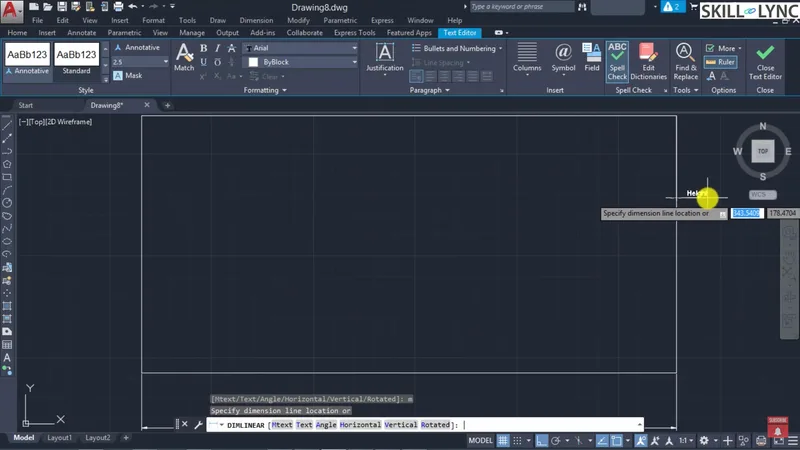
AutoCAD gives you the flexibility to customize dimension text through two primary commands: MText and Text.
- MText (Multiline Text): This option allows you to add multi-line text to dimensions, useful when you need to add additional information or formatting like bold, italics, or special characters. For instance, when dimensioning the radius of a circle, you can add a prefix like “R” for radius or suffix for additional notes.
- Text (Single Line Text): The Text option is simpler, allowing for single-line text, ideal for quick dimensions. You can easily override existing dimensions by typing in the desired value. This is especially helpful in cases where you want to highlight specific dimensions for inspection or reference.
Dimensioning Special Features
In AutoCAD 3D or complex 2D drawings, you may need to dimension arcs, angles, or chamfers. Here's how:
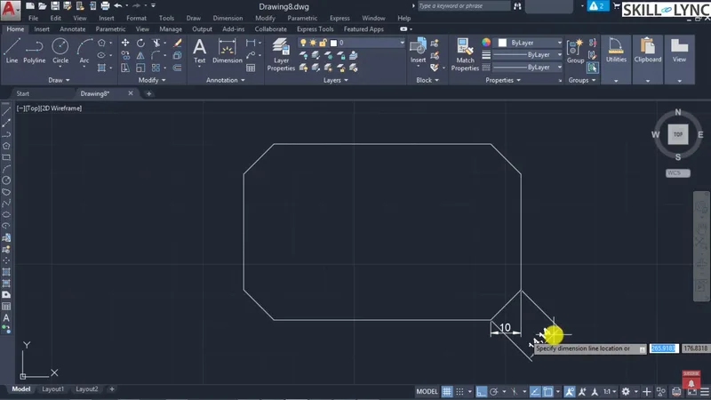
- Chamfer Dimensions: When creating a chamfer, you can specify the chamfer distance for each line. Using the linear dimension tool, you can measure the horizontal and vertical distances or the angled chamfer dimension.
- Angular Dimensions: For angular dimensions, you can select two lines or three points on an arc. The Angular Dimension command will automatically calculate the angle between them. You can also override the default alignment of the dimension text, allowing it to rotate for better readability.
- Radius and Diameter Dimensions: For circles and arcs, the Dimension Radius and Dimension Diameter commands are available. When applied, AutoCAD will place the dimension with an R (radius) or ⌀ (diameter) symbol, ensuring clear communication in your AutoCAD drawing.
Advanced Dimensioning Techniques
For more advanced dimensioning, AutoCAD provides tools like Baseline Dimensions and Aligned Dimensions. These are especially helpful when you need to maintain consistency in measurements from a reference point.
- Baseline Dimensions: Baseline dimensions allow you to create multiple dimensions from a single reference point. For example, if you are designing a stepped part, you can use baseline dimensions to mark each step from the same origin, ensuring accuracy.
- Aligned Dimensions: The Aligned Dimension command measures distances along sloped or angled surfaces. This is particularly useful when working with inclined features in mechanical autocad drawings.
Conclusion
Mastering dimensioning in AutoCAD is a fundamental skill for any engineer. Whether you're working with AutoCAD 2D drawings for beginners or more complex AutoCAD 3D models, understanding how to use dimensioning tools properly ensures that your designs can be accurately interpreted and manufactured. As you continue your journey in AutoCAD essentials, these tools will become invaluable for all your projects.
For those looking to further their skills, consider enrolling in an AutoCAD free class, AutoCAD free certificate course, or even an AutoCAD crash course. There are plenty of resources to help you become proficient in CAD design and stand out in the competitive field of mechanical engineering.
This blog is part of our ongoing AutoCAD Design Series. If you missed the previous posts, check them out here.
Would you like to have a more interactive experience going through the AutoCAD essentials?
Skill-Lync has released a FREE comprehensive course covering AutoCAD Essentials for Mechanical Engineers in detail! Check it out here.
If you’re looking to go deeper into AutoCAD Essentials check out Skill-Lync’s AutoCAD certification course.
Check out our hands-on course today and add AutoCAD to your list of skills!
Let’s get #IndustryReady together, one skill at a time!


