Exploring Scaling, Rotation and Constraints in AutoCAD
Boost your AutoCAD skills with this guide to scaling, rotation, and constraints in AutoCAD 2D and 3D. Essential for mechanical engineers, these techniques improve precision and efficiency, enhancing your CAD designs across projects.

Welcome back to AutoCAD Essentials for Mechanical Engineers blog series. In this blog, we’re focusing on block manipulation, specifically scaling and rotation, as well as constraint settings. These tools are essential for AutoCAD mechanical engineering projects, allowing you to optimize designs efficiently. Whether you're working on AutoCAD 2D drawings for beginners or more advanced 3D CAD designs, understanding these tools will enhance your productivity and precision.
Scaling and Rotation: Fine-Tuning Block Placement
In AutoCAD, the ability to scale and rotate blocks precisely is crucial for accurate design adjustments. Let’s dive into these functionalities with an example.
1. Setting Scale and Rotation:
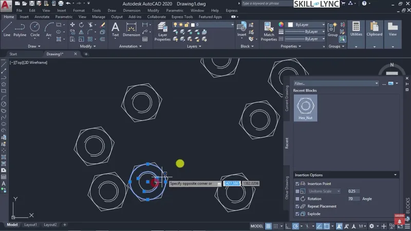
- Imagine we’re inserting a block with specific scale adjustments. For instance, we may set the scale on the X-axis to 25 while keeping Y and Z the same. This allows us to customize the block size dynamically for different uses.
- We also define a rotation angle, such as 45°. With this, the block can be rotated to align with surrounding components. This flexibility is essential for applications in AutoCAD 2D and 3D designs.
2. Dynamic and Preset Scaling:
- With dynamic scaling, you can adjust dimensions interactively, such as reducing the scale factor to 0.2 to fit tighter spaces in the design. For rotation, you can select a rotation angle directly (like 60° or 70°), allowing rapid adjustments. This feature is especially useful for AutoCAD for beginners and professionals alike, as it simplifies block manipulation in mechanical CAD programs.
3. Repeat Placement and Explode Commands:
- Using the repeat placement option, you can place multiple instances of the same block without restarting the command, saving valuable time. Additionally, the explode command allows you to break a block down into its original components for further editing. This feature helps when adjustments to individual elements within the block are needed.
Using the WBlock Command
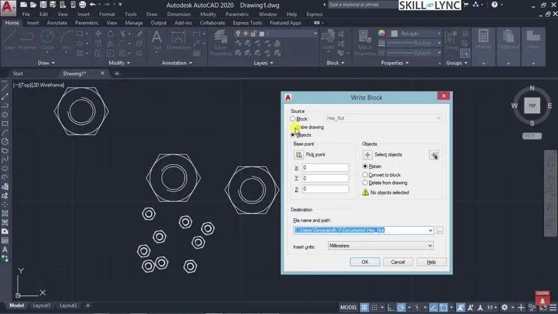
The WBlock (Write Block) command enables saving blocks as individual files. This is useful for sharing components across projects or with team members in different projects. Here’s how it works:
1. Specify the Block Source:
Begin by specifying the block to be saved. You can save the entire drawing as a block or select a specific block within the drawing.
2. Saving the Block as a Separate File:
Assign a file name and path for the new block file. For instance, if you’ve created a hex nut block, you might save it as HexNut.dwg.
3. Inserting External Blocks:
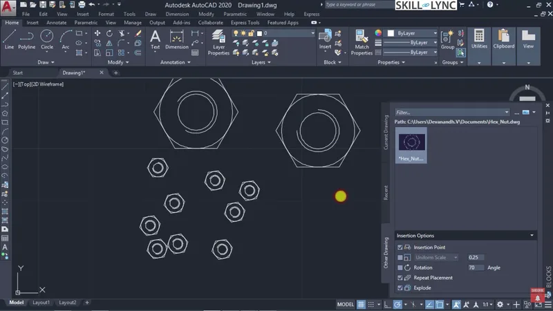
Once saved, you can insert these blocks into other drawings by selecting Insert Block. This function allows for efficient reuse of components, a significant time-saver in AutoCAD mechanical engineering courses and real-world applications.
Introducing Constraints in AutoCAD
To add even more flexibility to AutoCAD mechanical drawings, constraints allow you to define precise relationships between different objects. Let’s explore this with an example of a door mechanism.
1. Geometric Constraints:
Constraints prevent unintended modifications by locking specific elements in place. For instance, a door rotates around its hinge; it can’t move horizontally or vertically. In AutoCAD for engineers, similar constraints can be applied to blocks.
Common types of geometric constraints include:
- Coincident: Ensures two points remain coincident.
- Concentric: Maintains the same center point for circles, essential for components like shafts and bearings.
- Parallel and Perpendicular: Keeps lines parallel or perpendicular, critical in designing assemblies with specific geometric requirements.
2. Setting Up Constraints:
In the Parametric tab, you’ll find geometric constraints and dimensional constraints. Selecting Auto Constraint allows AutoCAD to apply constraints based on object types automatically. You can then fine-tune the constraints manually.
3. Prioritizing Constraints:
To control which constraints take precedence, you can modify the constraint priority in Auto Constraint settings. For example, the coincident constraint may be given the highest priority, while equal dimensions could be secondary.
Applying Constraints: A Practical Example
Imagine you’re designing a hex nut with a central circle and two concentric circles representing internal threads. Here’s how constraints keep this design consistent:
- Concentric Constraint: Ensures all circles share the same center.
- Tangency: Keeps specific lines tangent to curves or circles.
- Symmetry: Maintains a balanced design, crucial for components that must fit into larger assemblies.
Dimensional Constraints: Controlling Geometry
While geometric constraints focus on relationships, dimensional constraints manage the actual size and proportions of each component. Dimensional constraints can be defined using mathematical expressions and variables, adding flexibility for mechanical AutoCAD 2D drawing setups.
For example, setting a dimensional constraint between the internal diameter of a hex nut and its external face ensures that resizing one element proportionally adjusts the other. This feature is a powerful addition for anyone in AutoCAD training and certification courses, as it enables precise control over part dimensions.
Bringing It All Together
Understanding the scaling, rotation, and constraint features in AutoCAD is vital for mechanical engineers seeking to create efficient, consistent, and flexible designs. These tools streamline workflows in CAD design by reducing repetitive actions and enhancing design precision.
Whether you’re working on AutoCAD 3D crash courses or exploring AutoCAD online, mastering blocks and constraints will elevate your skillset. We hope this guide has enhanced your understanding of these essential CAD programs features. As you continue to develop your expertise, you’ll find these tools invaluable for both everyday tasks and complex projects in mechanical engineering.
This blog is part of our ongoing AutoCAD Design Series. If you missed the previous posts, check them out here.
Would you like to have a more interactive experience going through the AutoCAD essentials?
Skill-Lync has released a FREE comprehensive course covering AutoCAD Essentials for Mechanical Engineers in detail! Check it out here.
If you’re looking to go deeper into AutoCAD Essentials check out Skill-Lync’s AutoCAD certification course.
Check out our hands-on course today and add AutoCAD to your list of skills!
Let’s get #IndustryReady together, one skill at a time!


