


Modified on
A Comprehensive Guide to Performing Buckling Analysis in SolidWorks

Skill-Lync
Welcome back to our blog series on FEA Simulation using SolidWorks. In this post, we’ll dive into a crucial topic—buckling analysis—and walk through how to improve the buckling factor of safety for a bracket using SolidWorks FEA analysis. By the end, you’ll have a clearer understanding of the basic steps in FEA and how to approach this type of simulation using finite element method mesh techniques.
Let’s get started!
What is Buckling Analysis?
Buckling analysis is essential for determining how structures behave under compressive forces. When a structure is subjected to a load, it may buckle or collapse if the load exceeds a critical value. The buckling factor of safety is a key measure used to ensure that a design can handle the loads without experiencing catastrophic failure.
In this post, we’ll simulate buckling on a simple bracket and add a stiffener to improve its performance. This example will be particularly helpful for those following a SolidWorks FEA tutorial or those enrolled in a SolidWorks FEA course.
Basic Steps in Finite Element Analysis (FEA)
Before we get into the simulation, let’s quickly recap the basic steps in finite element analysis:
Model Setup: Define the geometry of the structure.
Material Assignment: Assign material properties to the model.
Meshing: Break down the model into smaller elements using a finite element mesh. In this case, we’ll apply both normal and controlled mesh to ensure accuracy in key areas.
Boundary Conditions: Define loads, constraints, and any external forces.
Run the Simulation: Execute the analysis and evaluate the results.
Post-Processing: Review results such as stress distribution, deformation, and safety factors.
Step-by-Step: Running a Buckling Analysis in SolidWorks
Here’s how you can apply SolidWorks FEA analysis to a simple bracket.
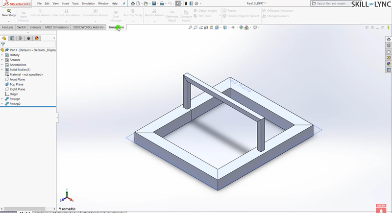
1. Model Setup
We’ll begin by opening the bracket in SolidWorks. A load of 2,000 Newtons (or 2 kN) will be applied on the top face, while the bottom faces of the bracket will be fixed.
2. Assign Material
For this simulation, a cast alloy steel is assigned as the material. You can adjust this depending on your specific requirements.
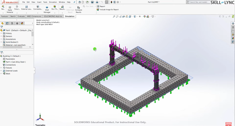
3. Meshing the Model
One of the basic steps in FEA is applying a finite element mesh. Here, a set of finer mesh for the area where most buckling is expected to occur and a normal mesh for the rest of the model. This allows us to capture higher accuracy where it matters most, while keeping computation time efficient.
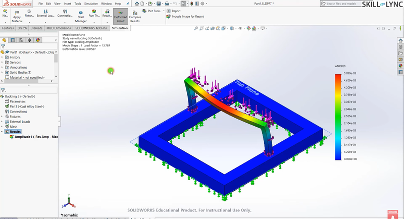
4. Running the Simulation
After meshing, buckling analysis is run. The result shows that the buckling factor of safety is 13.89 when a load of 2,000 Newtons is applied. While this is acceptable, our goal is to improve it to around 20 for added safety
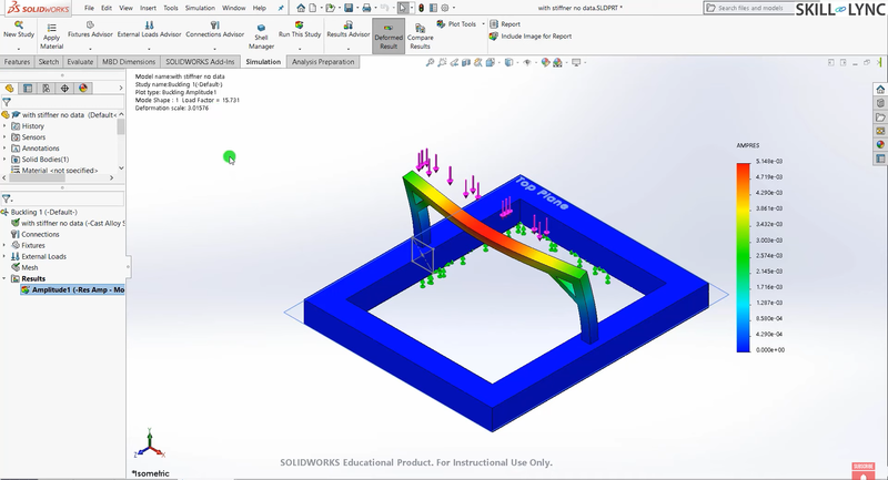
Adding a Stiffener to Increase the Buckling Factor
To increase the buckling factor of safety without changing the dimensions or material of the bracket, we’ll add a stiffener. This is a common technique in finite element analysis to improve a structure’s performance under load.
Once I’ve added the stiffener, we’ll rerun the simulation. Immediately, you can see an improvement—the buckling factor increases to 15.7, a significant gain just by adding a small stiffener.
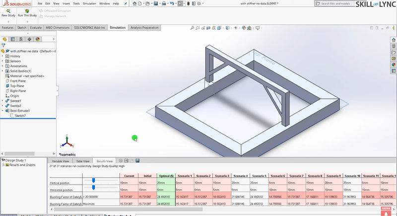
Design Optimization with Finite Element Mesh
We’re aiming for a buckling factor of 20, so let’s optimize further. Using SolidWorks’ Design Study feature, we can modify parameters such as the stiffener’s position, to find the most optimal configuration. This kind of finite element method mesh optimization allows us to achieve the best balance between structural strength and material usage.
After running the design study, we achieve our goal—an optimal buckling factor greater than 20! This demonstrates how a simple design modification can dramatically enhance the performance of your model.
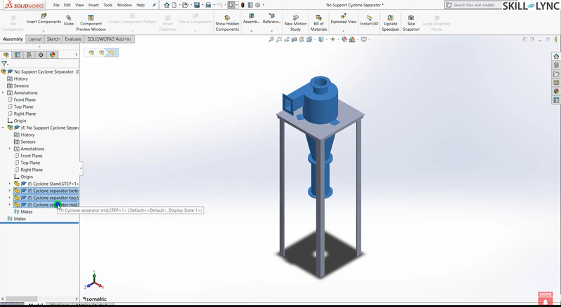
Your Buckling Analysis Challenge
For those following along with a SolidWorks FEA course, here’s a challenge for you! Using the same techniques outlined here, try increasing the buckling factor of safety for a cyclonic separator model. Your goal is to optimize the design without changing the material or dimensions, just like in our bracket example.
Focus on applying a finite element mesh effectively and experiment with stiffeners and other design features to improve performance.
Conclusion
SolidWorks FEA analysis is an incredibly powerful tool for optimizing designs and ensuring structural integrity. By understanding the basic steps in FEA and learning how to apply finite element method mesh techniques, you can significantly improve the safety and reliability of your models.
Whether you're learning through a SolidWorks FEA tutorial or participating in a SolidWorks FEA course, this example of buckling analysis provides valuable insights into how design changes can influence the outcome.
Keep experimenting, optimizing, and learning!
Stay tuned for the next post in our FEA Simulation using SolidWorks series!
This blog is part of our ongoing series on FEA Simulations using SolidWorks. If you missed the previous posts, check them out here.
Would you like to have a more interactive demonstration of the above concepts?
Skill-Lync has released a FREE comprehensive course covering FEA with SolidWorks in detail! Check it out here.
Right from the user interface's fundamentals, menus and options, this course covers most aspects of the tool from a practical perspective. It even includes a certificate to add to your resume after completion!
Check out our hands-on course today and add SolidWorks to your list of skills!
Let’s get #IndustryReady together, one skill at a time!
Author

Alda Rovina
Author
Skill-Lync
Subscribe to Our Free Newsletter

Continue Reading
Related Blogs
Explore the fundamentals of vehicle dynamics and ultimate trends in the field from design and modeling to control with Skill Lync's exclusive course on the subject. Read about how Skill-Lync's CAE courses can help you get employed.
28 Jul 2020
In this article, we will briefly discuss the working, applications, and features of the one-dimensional systematic simulation tool, GT-Power, in Emission Control Strategy, engine calibration, hybrid vehicle modeling. Read about how Skill-Lync's CAE courses can help you get employed.
28 Jul 2020
This article offers a brief introduction to the globally accepted standard of Geometric Dimensioning and Tolerancing, and its importance for the entire manufacturing process. Read about how Skill-Lync's CAE courses can help you get employed.
28 Jul 2020
In this blog we will read about Going a step into Biomechanics and how Skill-Lync's CAE course will help you get employed.
09 May 2020
The powertrain is the most prominent source of vibrations that affects the driving experience for the people on board. This blog from Skill-Lync examines these vibrations to help enhance that experience.
21 Aug 2020
Author
Skill-Lync
Subscribe to Our Free Newsletter
Continue Reading
Related Blogs
Explore the fundamentals of vehicle dynamics and ultimate trends in the field from design and modeling to control with Skill Lync's exclusive course on the subject. Read about how Skill-Lync's CAE courses can help you get employed.
28 Jul 2020
In this article, we will briefly discuss the working, applications, and features of the one-dimensional systematic simulation tool, GT-Power, in Emission Control Strategy, engine calibration, hybrid vehicle modeling. Read about how Skill-Lync's CAE courses can help you get employed.
28 Jul 2020
This article offers a brief introduction to the globally accepted standard of Geometric Dimensioning and Tolerancing, and its importance for the entire manufacturing process. Read about how Skill-Lync's CAE courses can help you get employed.
28 Jul 2020
In this blog we will read about Going a step into Biomechanics and how Skill-Lync's CAE course will help you get employed.
09 May 2020
The powertrain is the most prominent source of vibrations that affects the driving experience for the people on board. This blog from Skill-Lync examines these vibrations to help enhance that experience.
21 Aug 2020
Related Courses


