Wiring harness routing & packaging Rules Week 3 Challenge
Report:
Objective:
- To define the electrical properties of Supports, Back shell and Corrugated Tubes using Electrical Part Design.
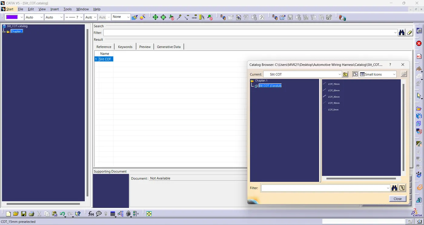
- To add the corrugated tubes in catalogue under Slit COT family.
Introduction:
1.Electrical Support:
- Electrical support is a part which provides support for the electrical components.
2.Back shell:
- Back shells are the components that attach to the back of connectors often designed to guide the wires and cables that are terminated at the connector. The back shells are often mated with strain relief components, environmental seals, the shielding.
3.Corrugated Tubes:
- Convoluted tubing is primarily used to protect cabling. Depending on the intended use, corrugated tubing is manufactured in different diameters and from different materials.
- Graphical representation of corrugated tubes applied on the bundles.
Parts:
- P clamp
- Back shell
- COT Tubes
Design Methodology:
1. P clamp:
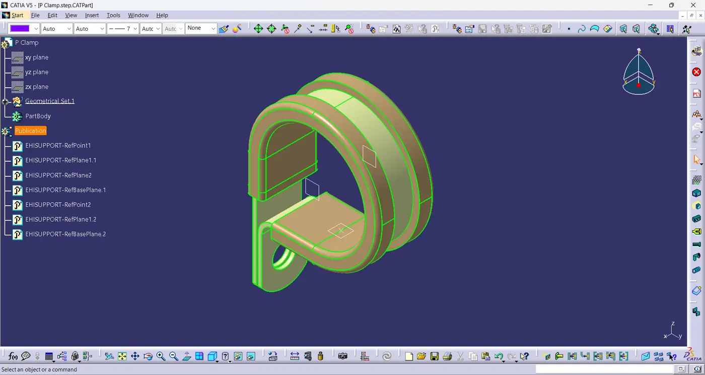
- First step is to download the .igs file and convert it into .CATPart file.
- The required Geometrical parameters such as Entry, Exit & Base plane is defined.
- Define the P clamp as support part using Define support command by selecting the entry plane as first plane ,entry plane origin as point, exit plane as second plane and base plane.
- Again define the p clamp using define support command by selecting the the exit plane as first plane, exit plane origin as point, second plane is pre-defined as exit plane by system and base plane.
2.Back shell:
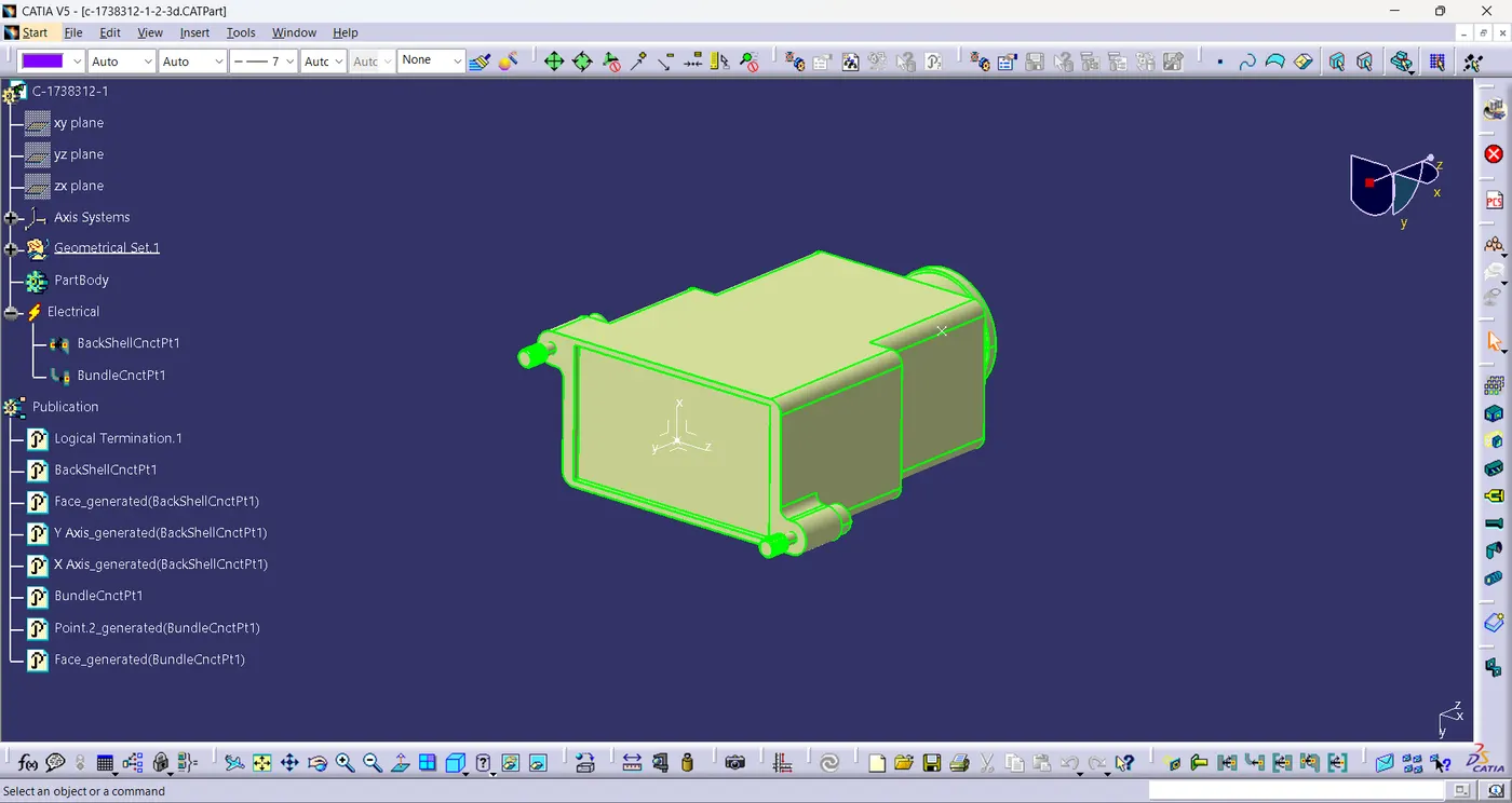
- First step is to download the .igs file and convert it into .CATPart file.
- The required geometrical parameters like point on entry & exit of back shell, axis on the mating face of the back shell are defined.
- Define Back shell using back shell command by selecting the body.
- Define the Back shell connection point using define back shell command by selecting the representation as point on the exit of back shell as representation, back shell mating face ,Coincidence & orientation axis
- Define Bundle connection point by selecting representation and initial condition as the normal face and select the midpoint as point of back shell.
3.COT Tubes:
- Create a catlog document, add family and save it. Then create sub part family.
- A catalogue is created under Slit COT family.
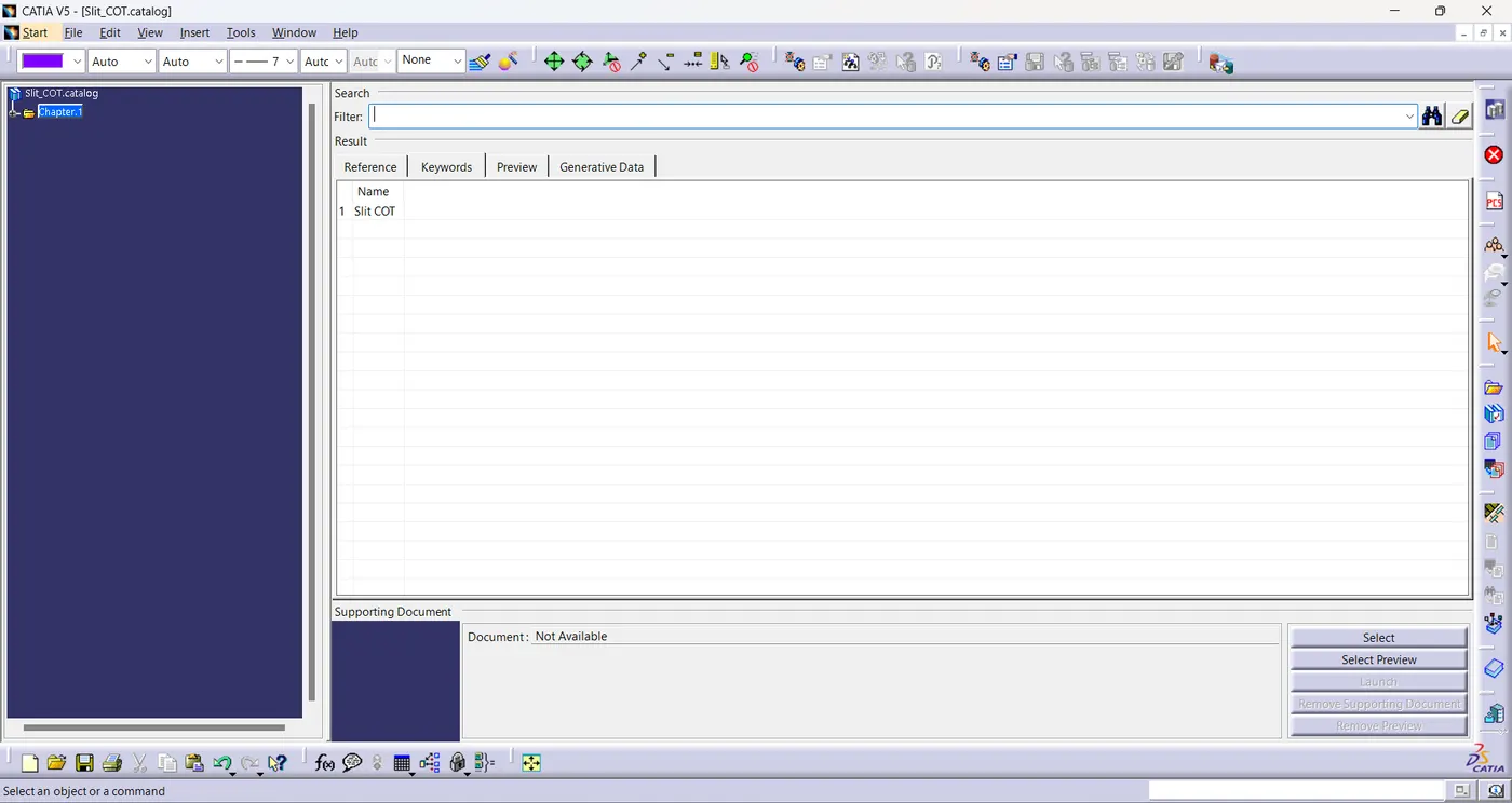
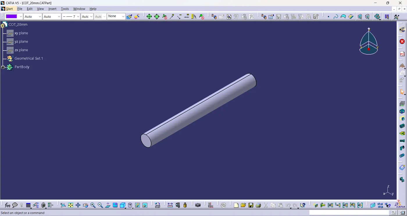
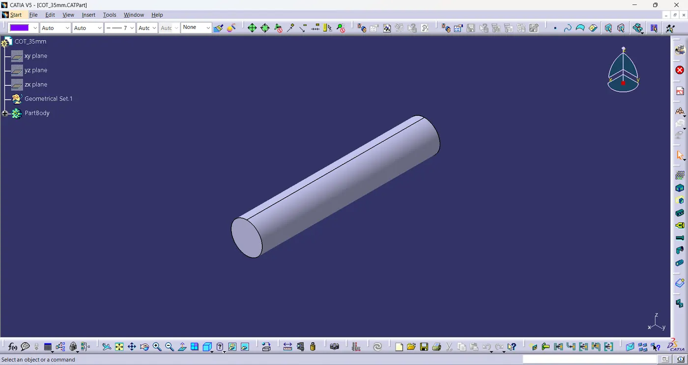
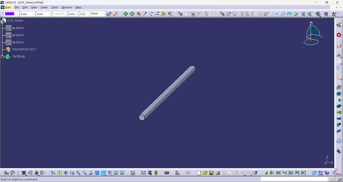
- Then create COT Tube of the various dimensions given below using the command define protection part.
Name | ID (mm) | OD (mm) | Thickness (mm) |
15mm COT | 12 | 15 | 1.5 |
20mm COT | 17 | 20 | 1.5 |
35mm COT | 32 | 35 | 1.5 |
10mm COT | 7 | 10 | 1.5 |
5mm COT | 3 | 5 | 1 |
i. COT 15mm
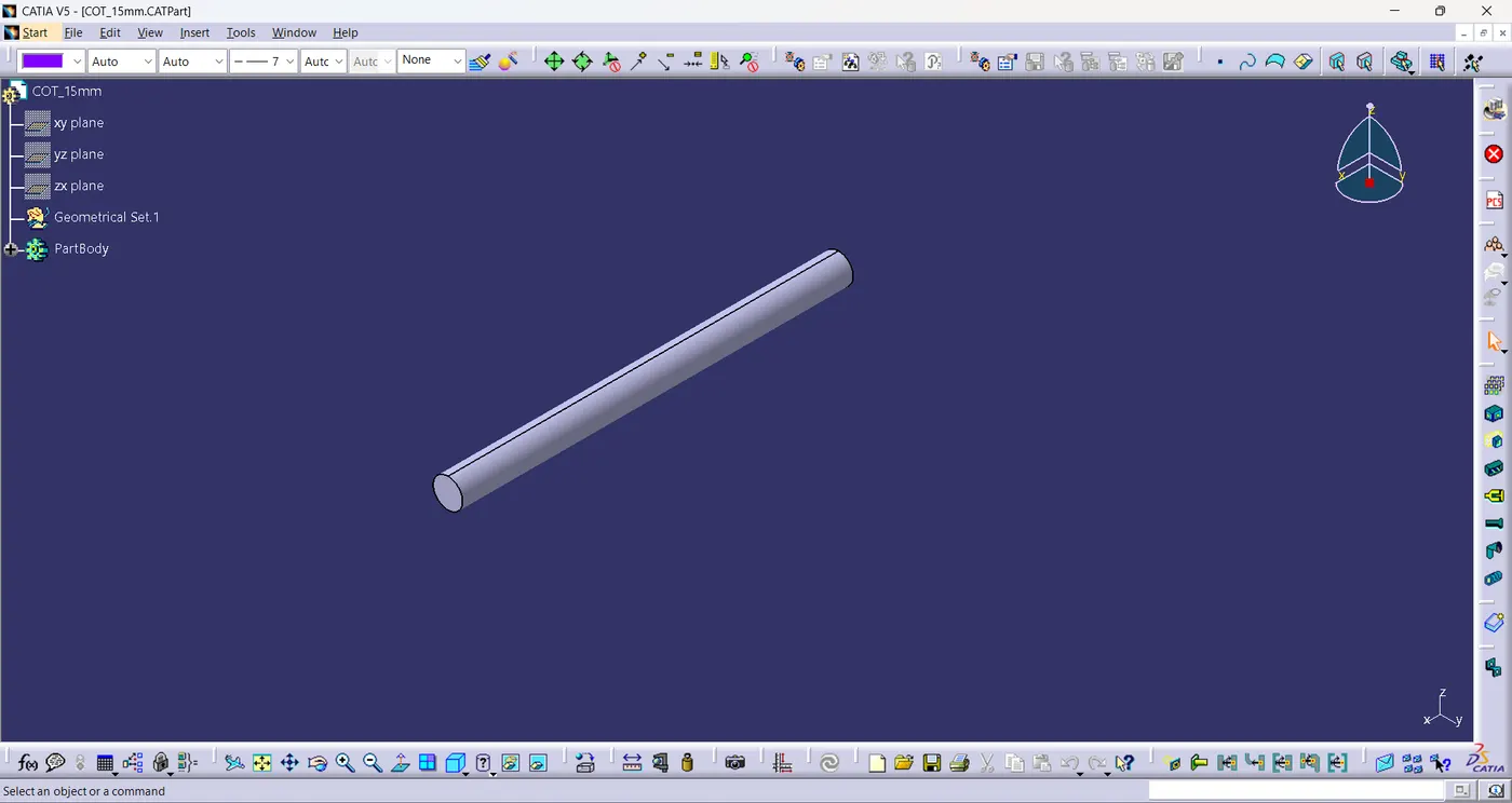
ii. COT 20mm
iii. COT 35mm
iv. COT 10mm
v. COT 5mm
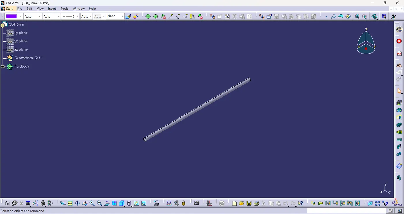
- All the 5 corrugated tubes are added under Slit COT family in catalogue.
Conclusion:
- All the necessary electrical properties of P clamp, Back shell and Corrugated Tubes are defined using electrical part design workbench.
- The corrugated tubes are added in the catalogue under Slit COT family