Wiring harness routing & packaging Rules Week 3 Challenge
Wiring Harness Routing & Packaging Rules - Week 3 Challenge
OBJECTIVE: The given CAD data should be downloaded from the provided link to define all the necessary properties of the P Clamp and the Backshell and finally create corrugated tubes of various sizes and add them to the catalogue.
Exercise -1: P Clamp
Given Data:
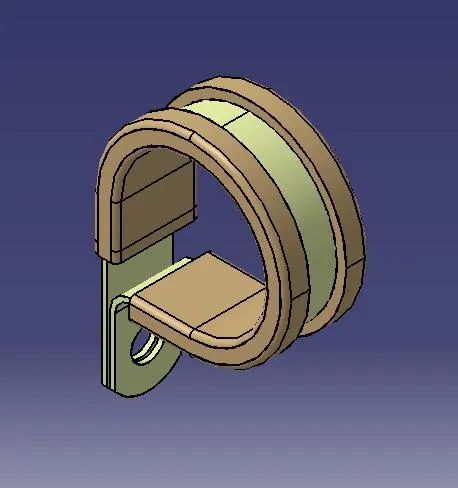
Steps to be followed:
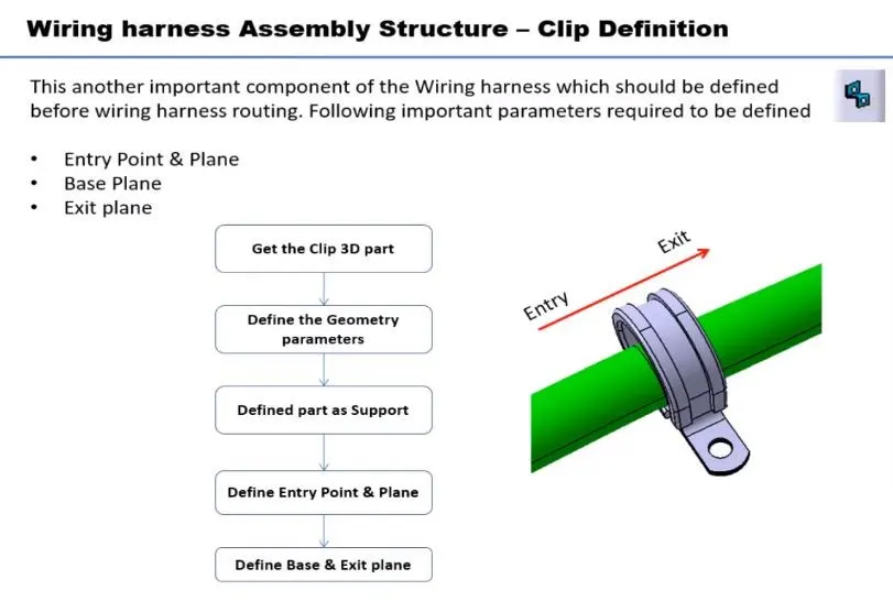
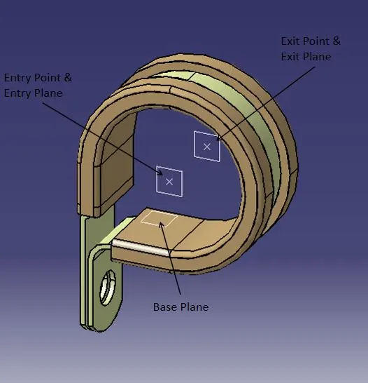
STEP-1: Bundle Entry & Exit Points and its Planes
Based on the P Clamp position, create a midpoint on either side of the P Clamp to serve as entry and exit points for the bundle. Subsequently, generate entry and exit planes at these points, oriented perpendicular to the bundle.
STEP-2: Base Plane
Create a base plane with an offset based on the bundle diameter on the P Clamp.
Switch to the Electrical Part Design
STEP-3: Define Support Part
Define the CAT Part as a Support using the Define Support Part option and define the properties as shown below.
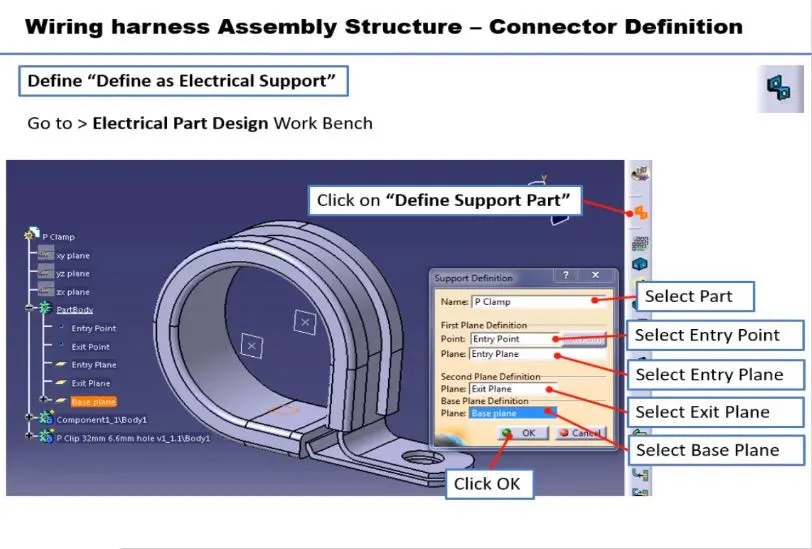
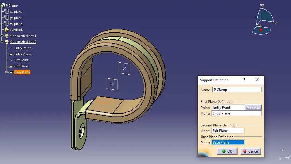
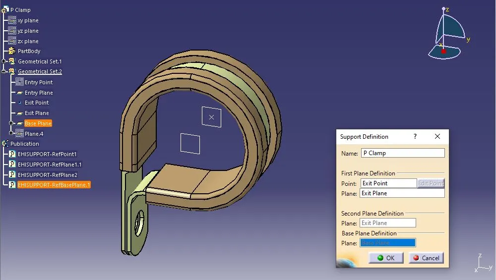
Again define the CAT Part as a Support using the Define Support Part option and define the properties as shown below.
Exercise -2: Back Shell
Given Data:
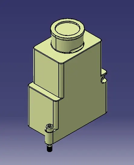
Steps to be followed:
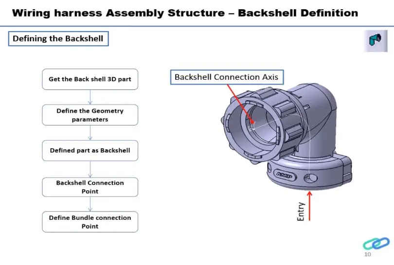
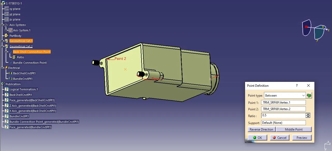
STEP-1: Back Shell Connection Point
Create a midpoint on the back shell surface that will attach to the connector.
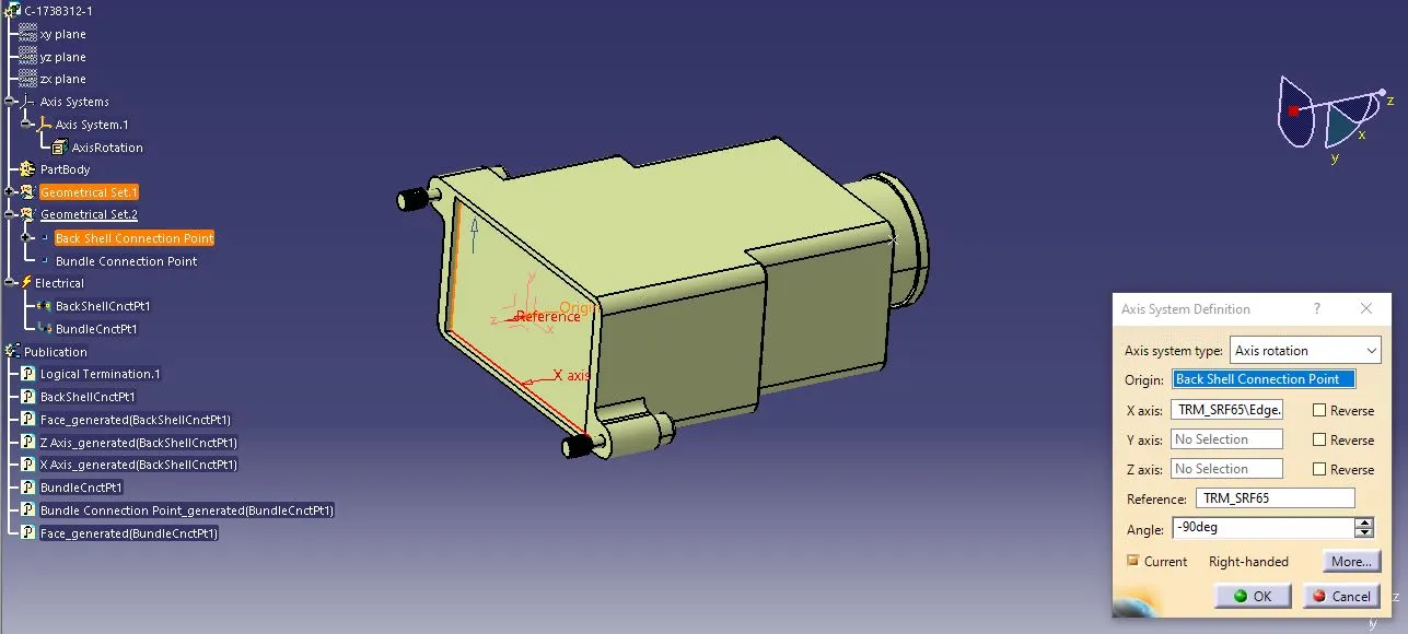
STEP-2: Back Shell Axis System
Create an Axis System to the back shell connection point as defined below.
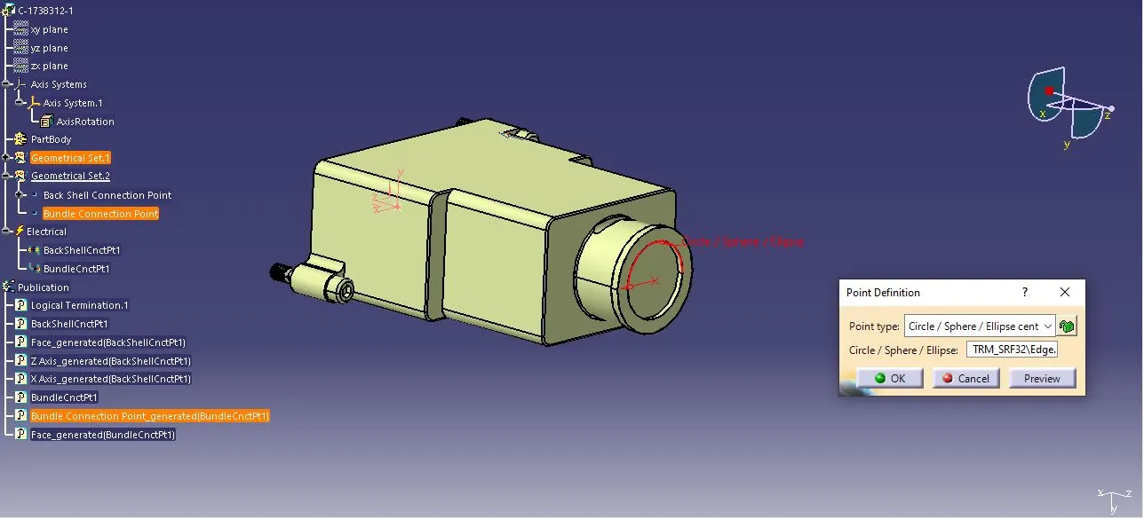
STEP-3: Bundle Connection Point
Create a midpoint on the contact face which is normal to bundle wire direction.
Switch from Mechanical Part Design to Electrical Part Design
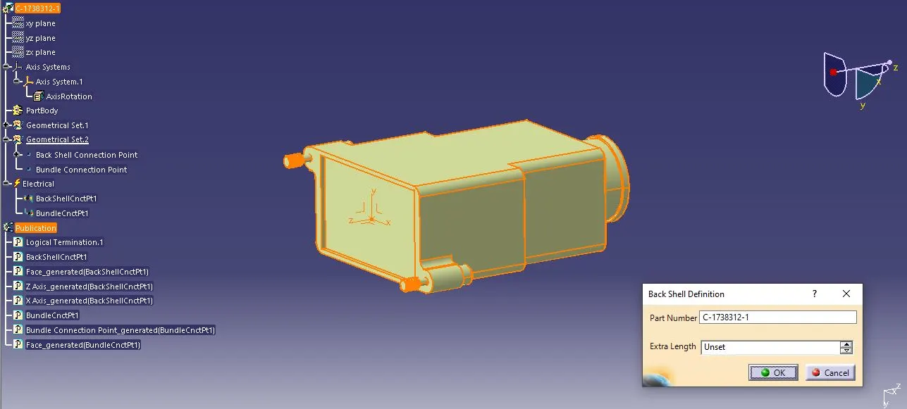
STEP-4: Define Back Shell
Define the CAT Part as a back shell using the Define Back Shell option and mention the extra length as unset.
STEP-5: Define Back Shell Connection Point
Choose the Define Back Shell Connection Point option and select the back shell connection point as representation. Then, define the placement constraints as below.
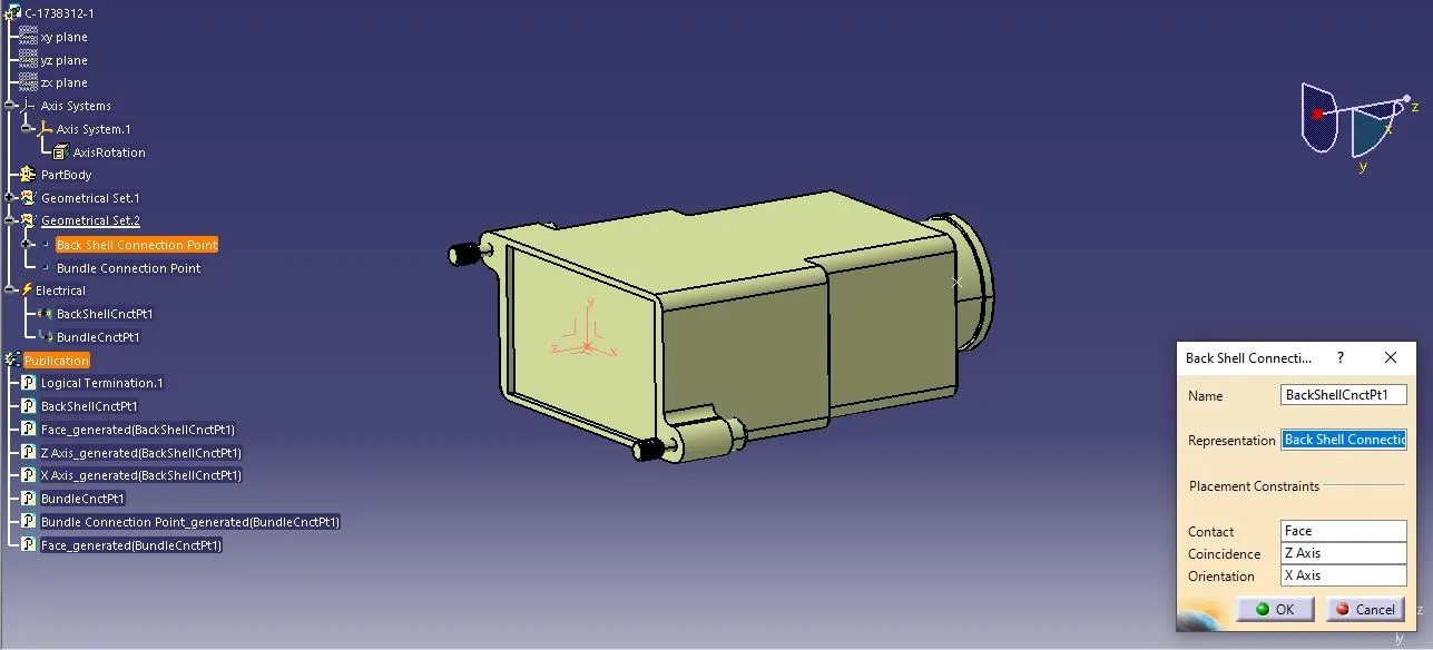
STEP-5: Define Bundle Connection Point
Choose the Define Bundle Connection Point option and select the bundle connection point and the contact face as below.
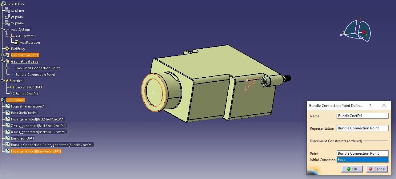
Exercise -3: Corrugated Tubes
STEP-1: Open a new part file and switch the workbench to Electrical Part Design.
STEP-2: Define Protective Part
Define all the specifications for the desired corrugated tubes. Now, the specs are given for OD - 15mm; ID - 12mm; Thickness - 1.5mm. The bend radius is calculated by 1.5 times of OD.
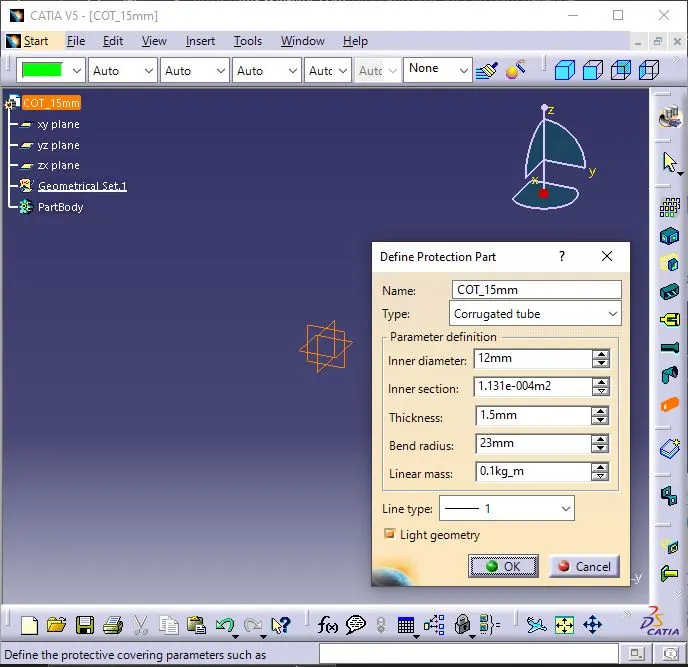
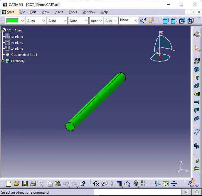
STEP-3: Catalogue Creation
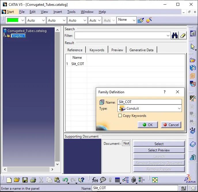
Open a new catalogue document file. Now, add the Family as Slit_COT and then save it.
STEP-4: Tag the file to the Catalogue
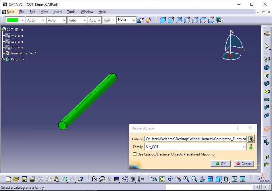
Once the catalogue is created, save the file. Now, choose the Storage Device option and select the Familt as Slit_COT.
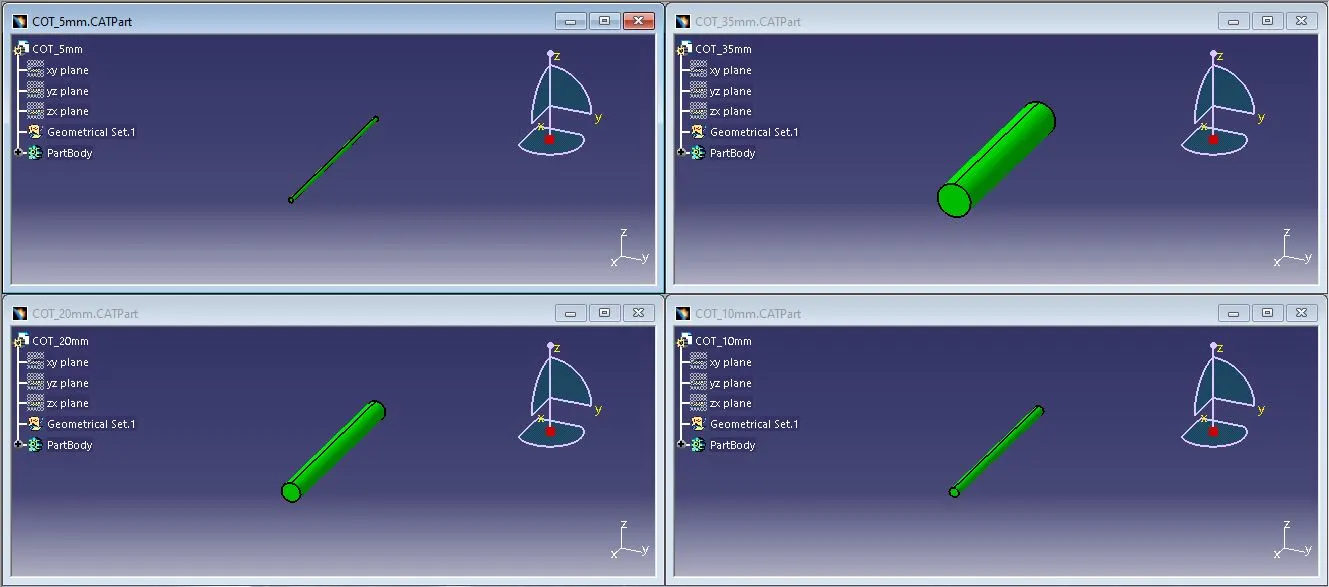
STEP-5: Now repeat Steps 2 & 4 to create various sizes of corrugated tubes.
Conclusion:
Thus downloaded all the necessary CAT data and performed all the exercises.