Wiring harness routing & packaging Rules Week 3 Challenge
DEFINING THE P CLAMP AND THE BACKSHELL FROM MECHANICAL TO ELECTRICAL PART AND CREATING THE CORRUGATED TUBES AS PER REQUIREMENT:
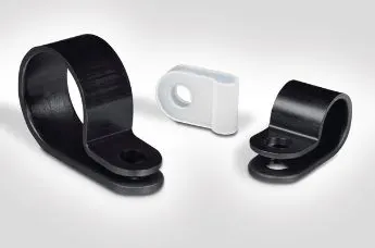
P Clamp: P clamps also known as P-Style or R- Type are designed to assist in bundling and clamping applications for pipes, hoses and wires. Available in various materials and sizes, these screw mount clamps are stocked in a choice of different mounting hole and screw sizes dependent on your application and requirements.
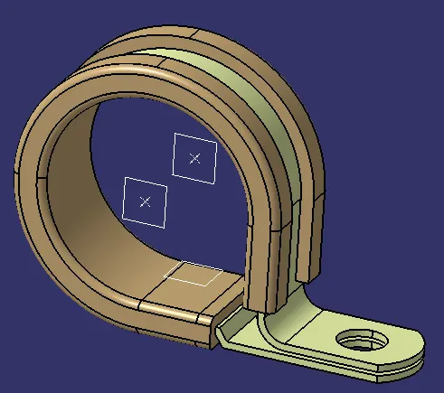
for the P clamp we have 2 entry point and exit point so we will define both the entry and exit point by creating point and plane.
First we will create a centre point on the both the entry side and and then we will create 3 plane two plane on the two points and then we will create another lane on the base beacause for defining the P clam we need 3 planes and 2 points since it is a 2entry and exit point
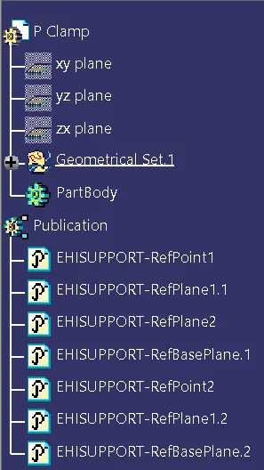
after creating the point and plane we have to define this P clam as a electrical part for that we will use define support part command and then we will define the part using the points and planes.
we will define it twice using the define support part command because the P clamp have two entry and exit points.
once if we defined it twice then our P clam is a electrical part completely and we have also defined entry and exit points.
now we will define the back shell for the connector.
BACKSHELL: A backshell is an accessory that mounts to the rear threads of a connector to enhance its operational characteristics. The primary function of a backshell is to provide strain relief, which minimizes stress from the cable, on the junction where the wires terminate to the contacts.
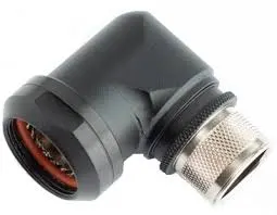
for defining the back shell first we will create some geometries to it so that we can define the connection points.
first we will create two points one point is for the bundle connection point and anothe for backshell connection point.
and then we will create a axis system on the backshell connection point and then we will place the x axis as per the locking direction and we will place y axis on the mating direction and zaxis on the other direction. After placing the axis system we will define the back shell using define backshell command and we will define the back shell and then we will use bundle definition point command and then we will define the bundle connection point and then we will use define backshell connection point command and we will define the backshell connection point.
once if we done upto this much our backshell is defined completely.
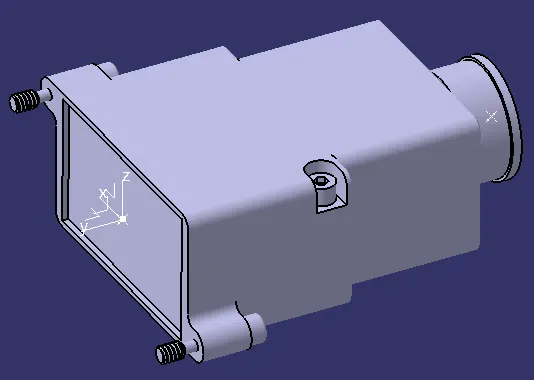
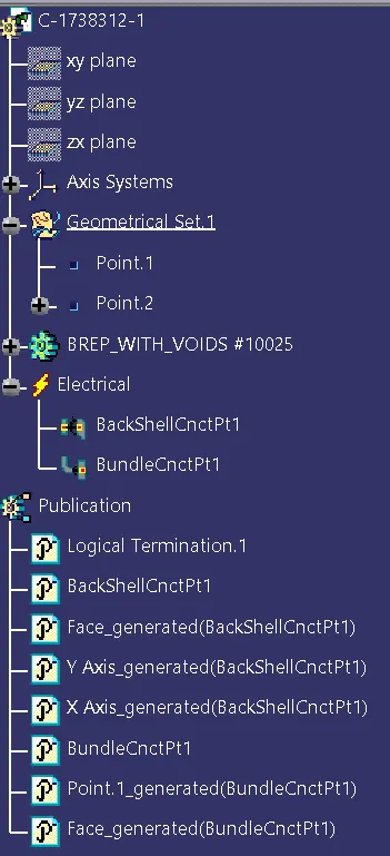
now we will create the corrugated tubes as per requirement:
CORRUGATED TUBES: A corrugated tube is a pipe with a helical groove obtained from a plain tube by cold forming. The number of starts of the helix can be changed as well as the angle to optimize the heat transfer and performance.
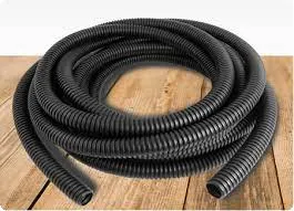
for creating the corrugted tube we just need the inner dia and the thickness of the tube and it is very simple to create the corrugated tube.
first we will open electrical part design workbench and then we will use define protection part command and then we will just click on the part body and a window will popup the popup window will be as follows:
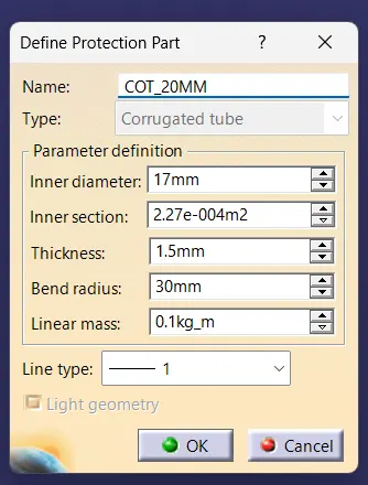
in this window we will adjust the inner diameter and the thickness and the bend radius for example if the inner diameter is 15mm and the thickness is 1.5mm then we have to give the bend radius as 1.5times of the outer dia.
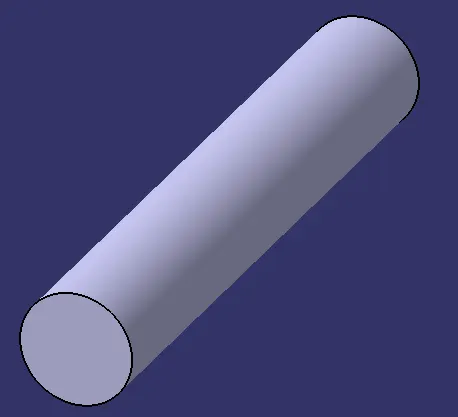
once if we given the required dimensions then we will recieve the output as follows:
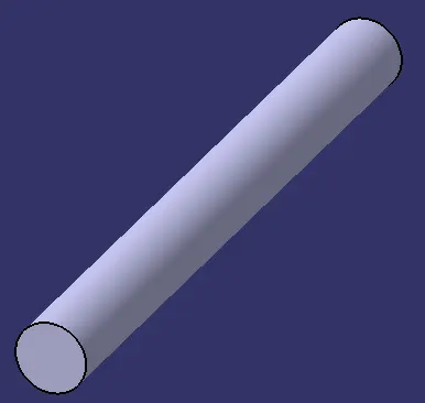
once if we done upto this much we have completed the creation of corrugated tubes.
we will create various corrugated tubes by giving different inner dia and the bend radius according to our requirement.
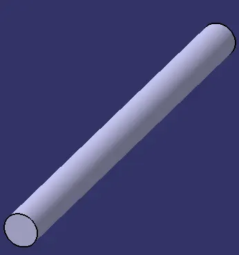
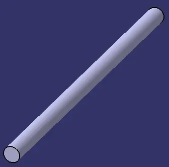
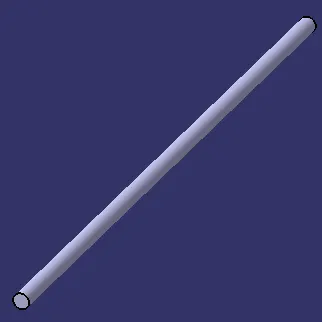
following are the various corrugated tubes created: