Wiring harness routing & packaging Rules Week 3 Challenge
Wiring harness Routing and packaging Rules-Week 3 Challenge
AIM:
- To define mechanical component electrically and prepare the catalog for the same.
- Prepare the COT tube and make the catalog for the same.
- Prepare a report with all the required images for the challenge.
INTRODUCTION:
- P-Clamp: A P-clamp also known as a P-clip, is a type of clamp that is used to secure and route wires in the wiring harness. P-clamps are named for their distinctive P shape which created by metal base with rubber coating and hinge or fixed loop.
- Back shell: A back shell is a connector accessory that fits over the back of the connector in the wiring hardness to provide support and protection for the wires and connectors.
- Corrugated Tube: A COT tube or corrugated tube is a flexible, bellows-shape covering used to protect varying harness.
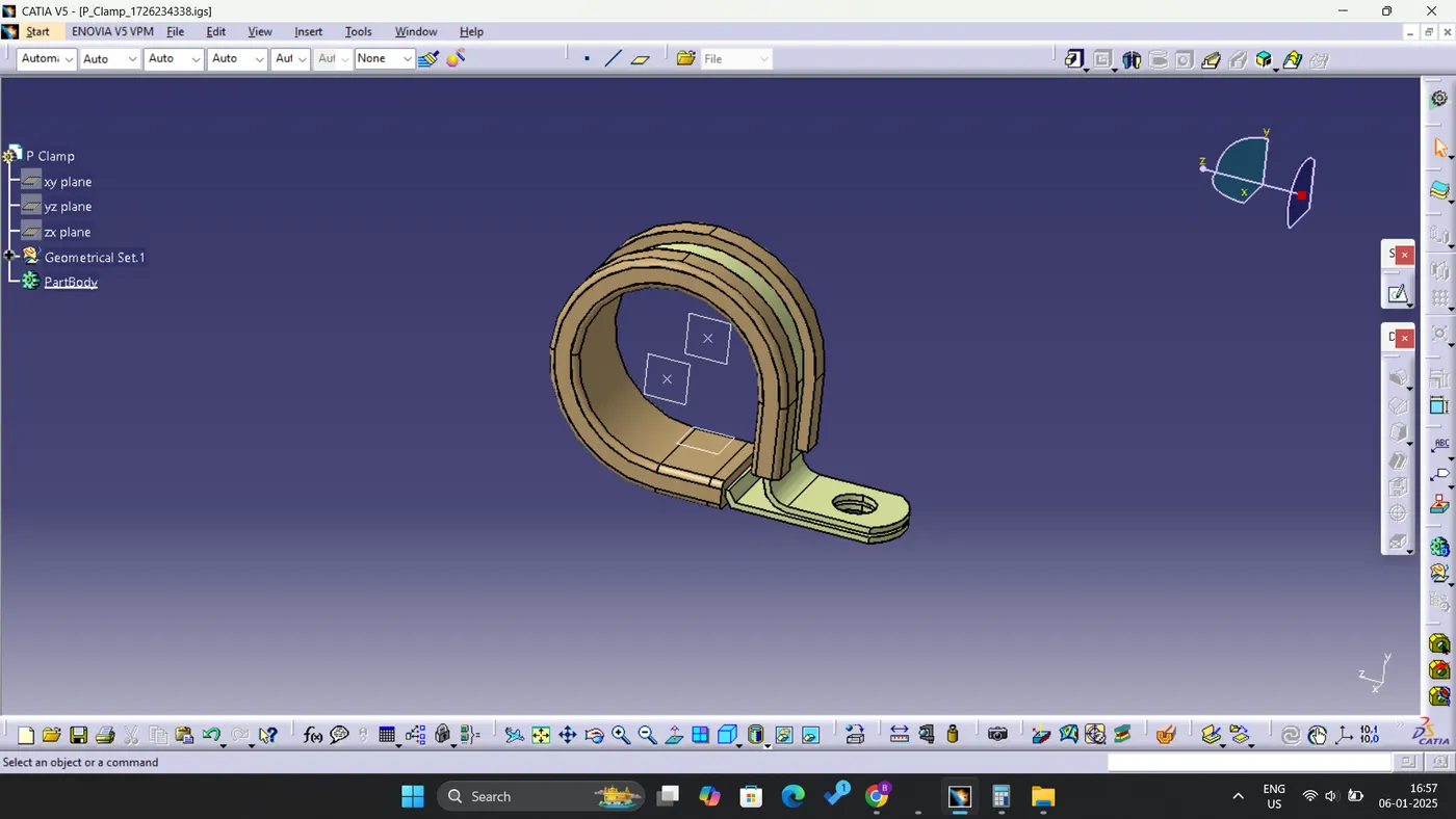
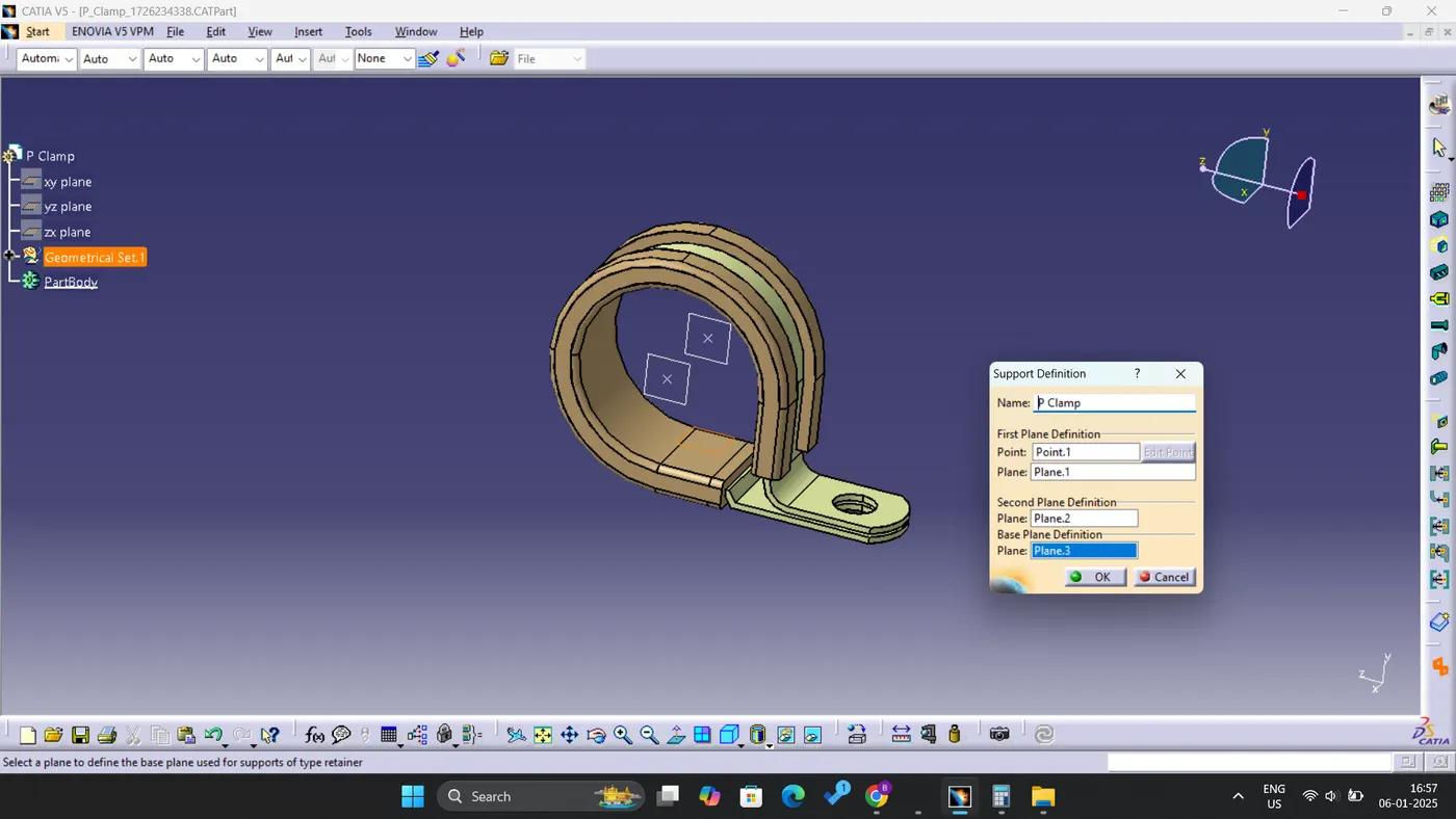
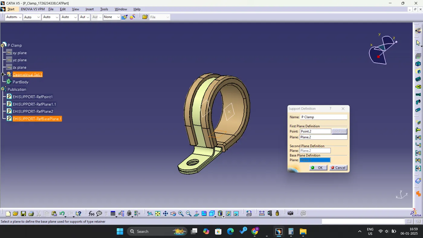
Q1. Download the following P-Clamp CAD data & define it as Electrical support using the Electrical Part Design Workbench. Define all the necessary properties.
- To create Points and the Planes in the Part Design Workbench, one must initially define the component as a support within the Electrical Part Design Workbench.
- It is essential to select the appropriate point and plane for the first entry point, as well as to designate the exit plane and the base plane.
- Following this, the procedure should be repeated to select the point and plane for the second entry point.
- The exit plane will be automatically designated, and the base plane must be chosen accordingly.
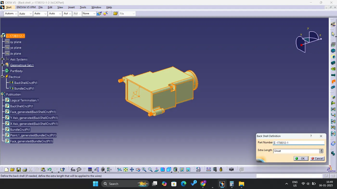
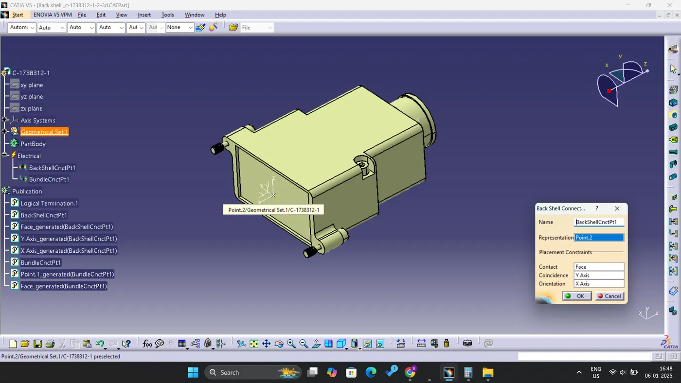
Q2. Download the following Back shell CAD data & define it as an Electrical back shell using an Electrical Part Design Workbench. Define all the necessary properties.
- To create Points and the Planes in the Part Design Workbench, initiate the process by defining the part as a support within the Electrical Part Design Workbench.
- Proceed to select both the point and plane for the first entry point, and subsequently choose the exit plane along with the base plane.
- Similarly, for the second entry point, select the corresponding point and plane; the exit plane will be automatically designated, and you will need to choose the base plane.
- After completing these steps, transition to the Electrical Part Design Workbench.
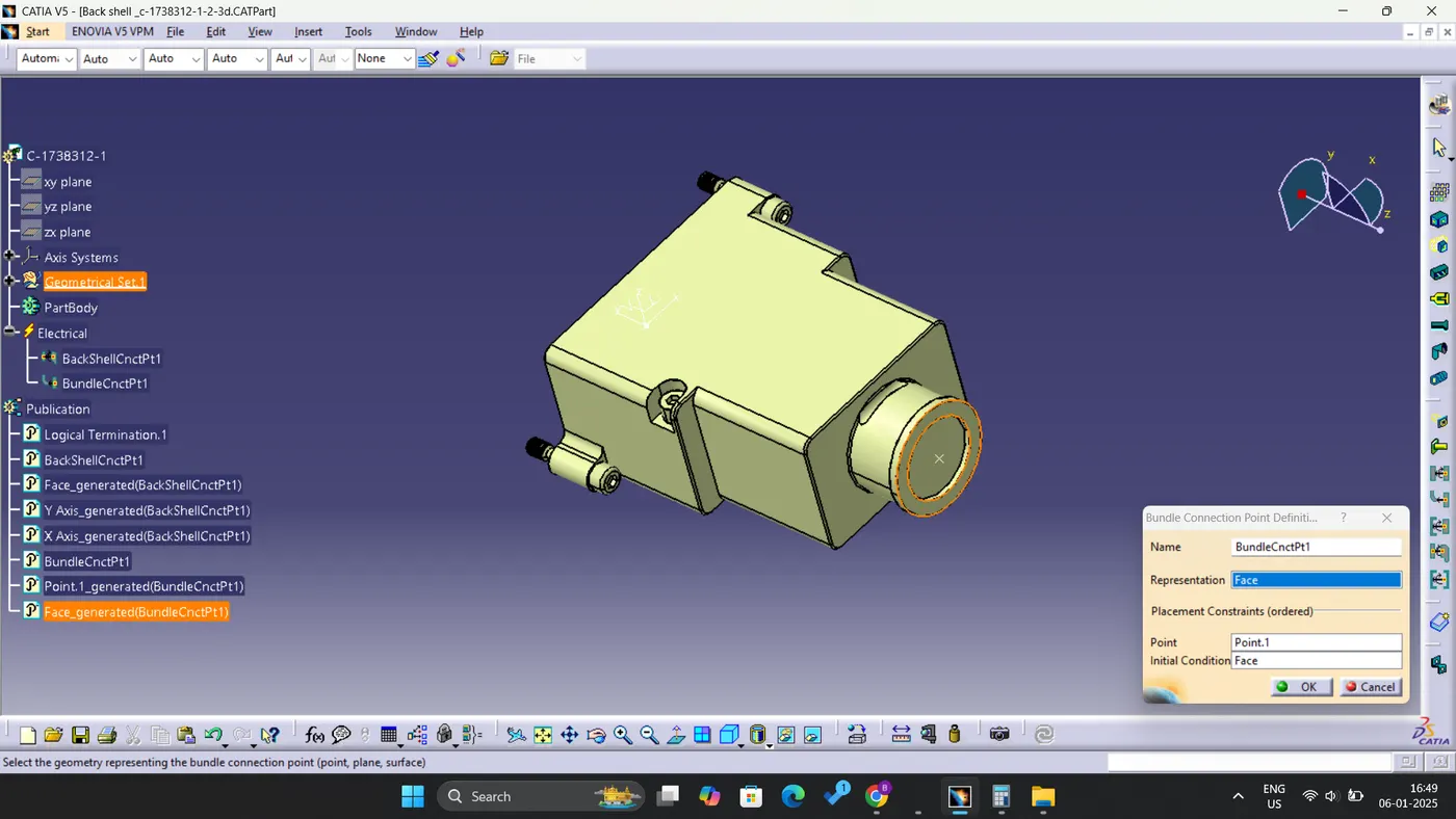
- Define the component as a back shell, establish the back shell connection point, and designate the bundle connection point accordingly.
Q3. Create the Following Corrugated tubes & Add them to Catalogue under the “Slit COT” family.
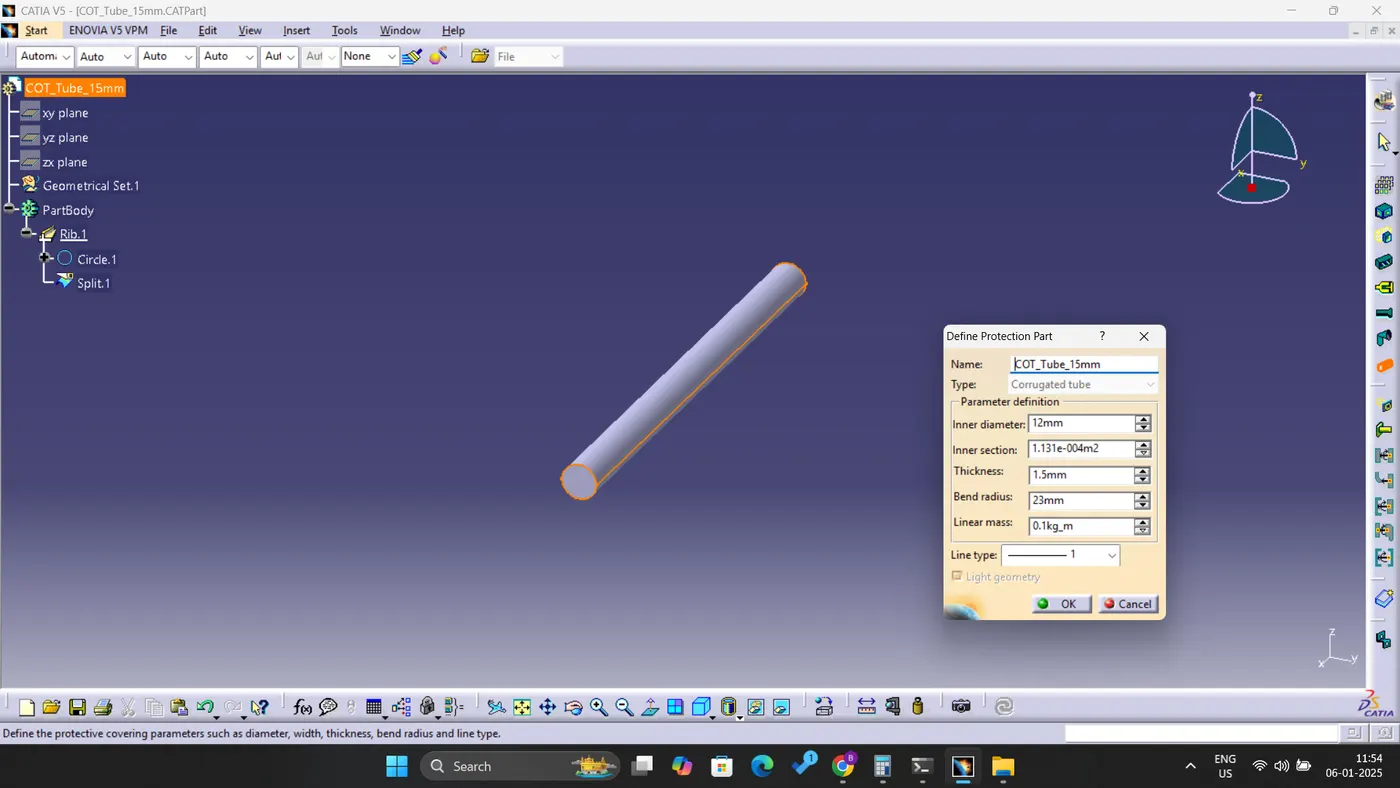
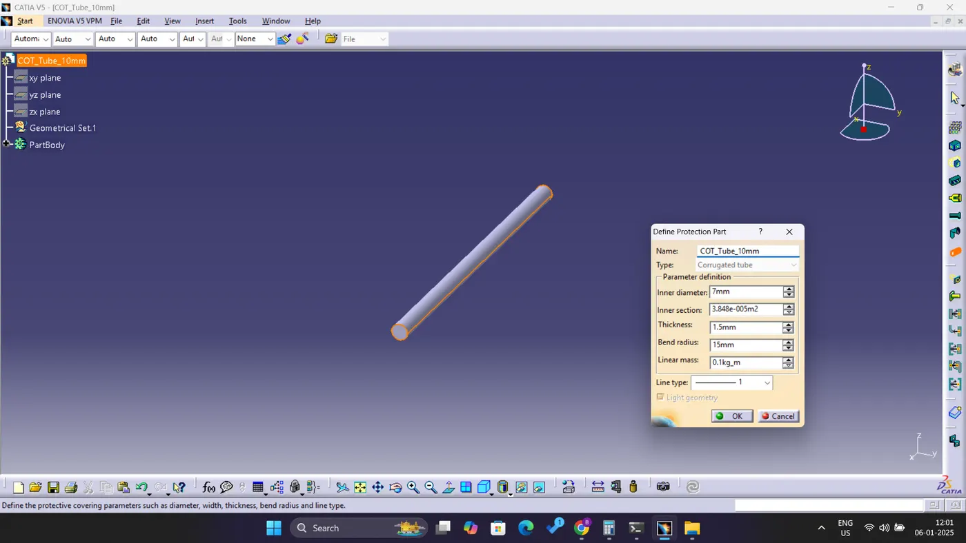
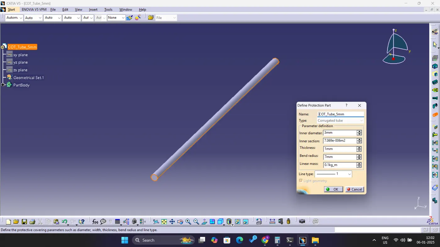
- To initiate the creation of a new part, please transition to the Electrical Part Design workbench.
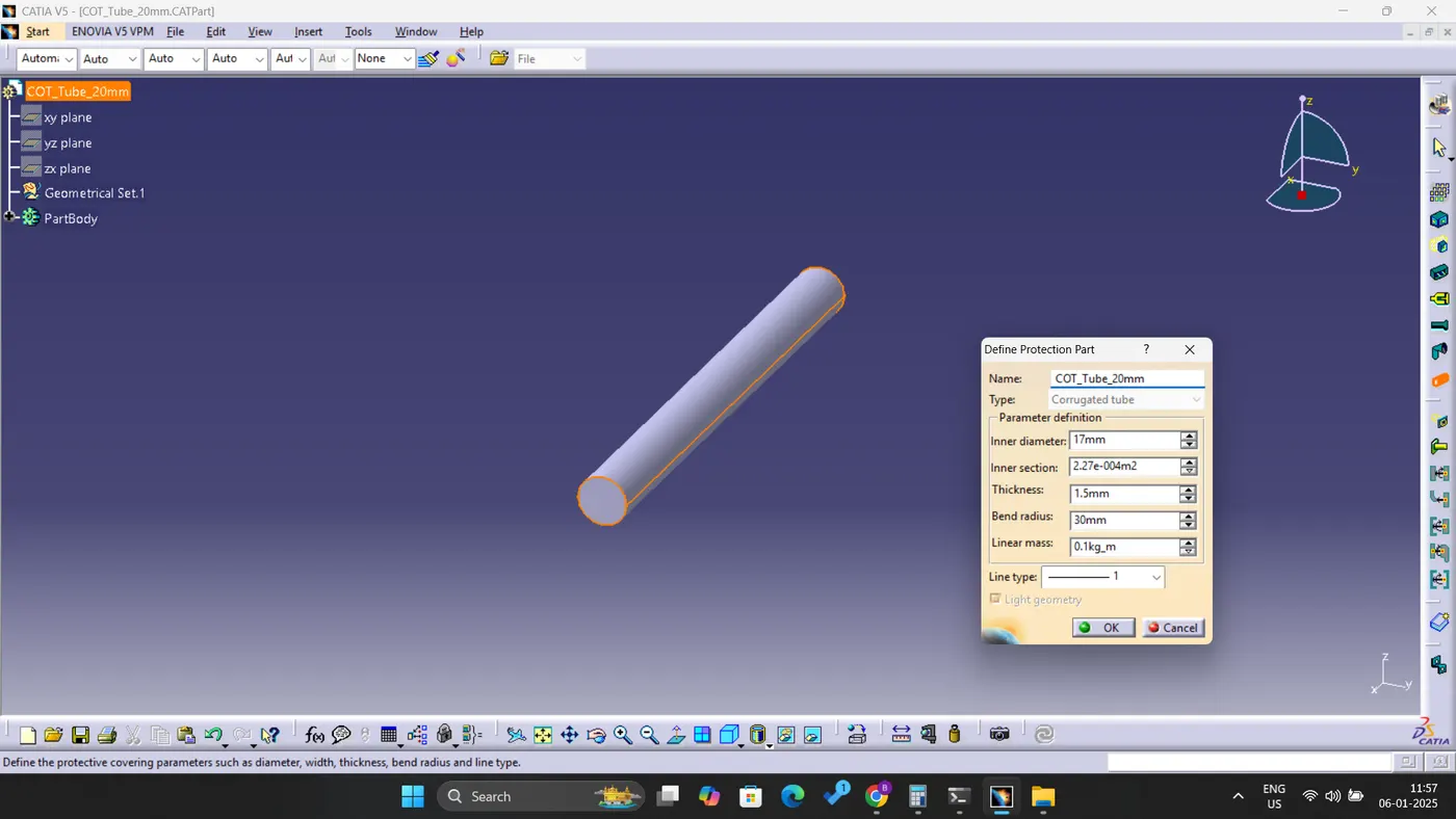
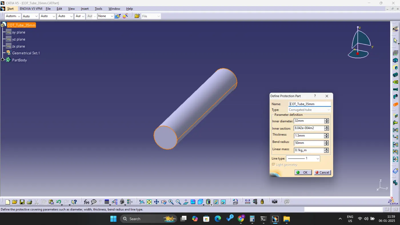
- Define the Protection Part by inputting the parameters as specified in the provided chart.
- Additionally, ensure that the bend radius is maintained at 1.5 times the diameter.
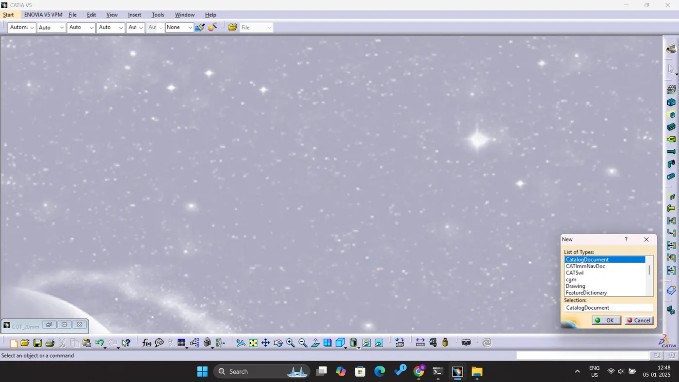
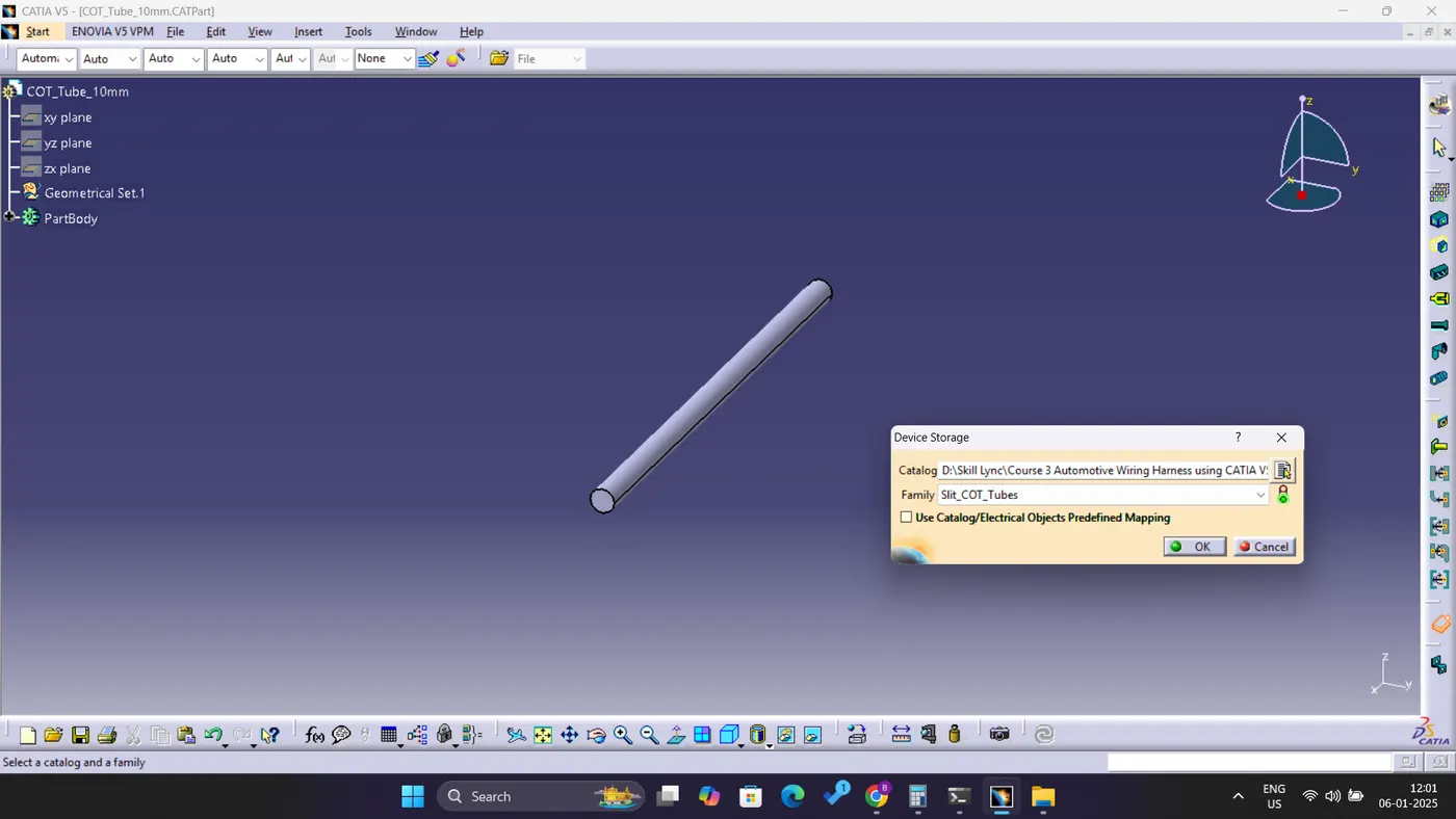
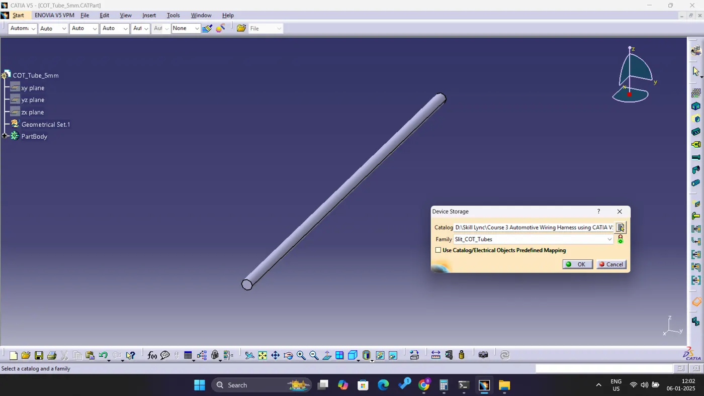
- For catalog creation, execute the following steps: Navigate to File, select New Part, and then choose the catalog document option.
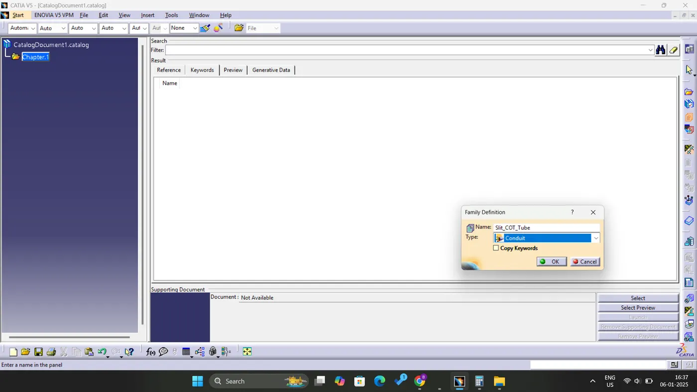
- Add a Family by providing a suitable name, and select the Type as Conduit before saving.
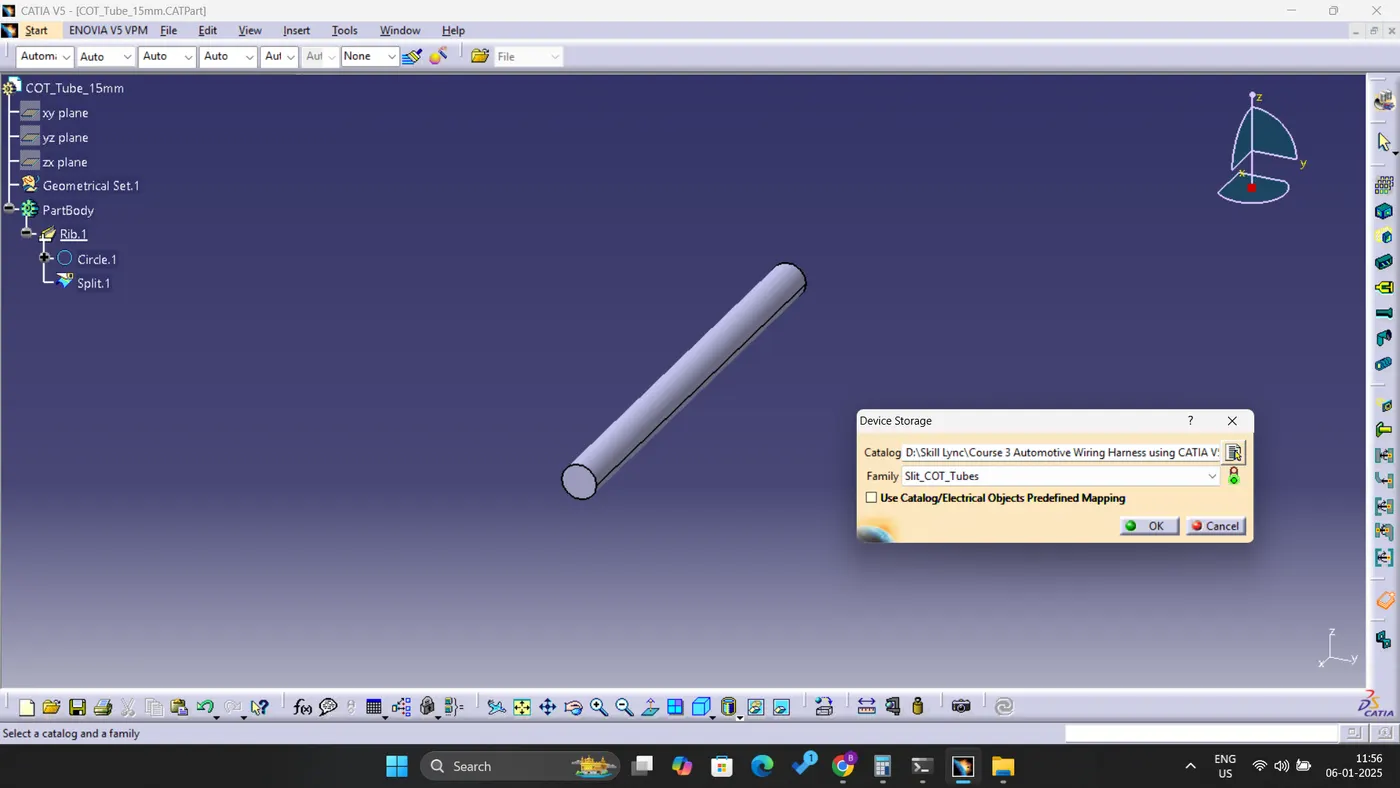
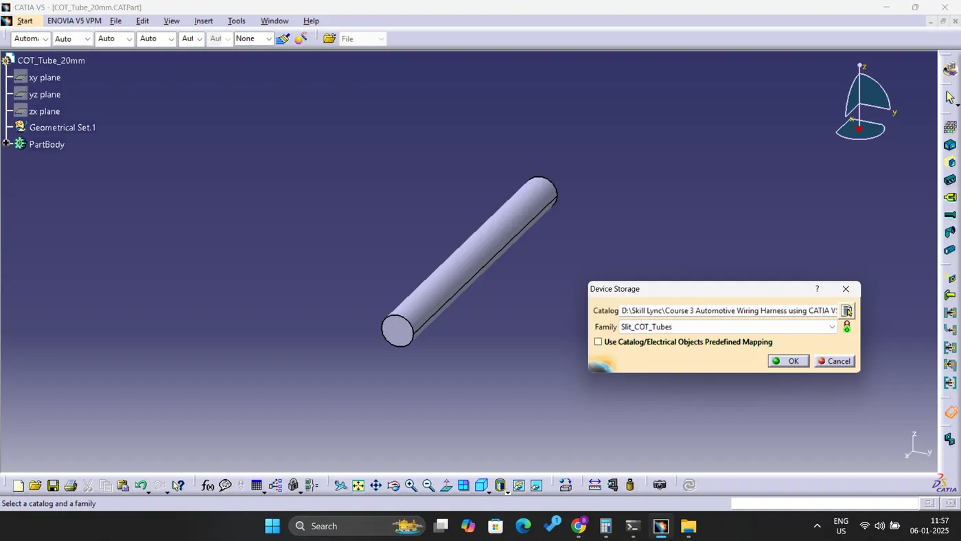
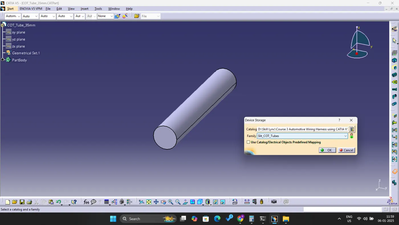
- Subsequently, access the Part (COTs Created) section, and utilize the Store Device Command to select the Catalogue family and the corresponding part.