Wiring harness routing & packaging Rules Week 3 Challenge
CHALLENGE WEEK - 03
Aim: In the following challenge we need to download the cad part files provided in the question and create the required geometrical parameters and define the part as the electrical part and craete the catalogue required.
Objective: The main objective in the question is to download every cad file and amke the support changes
Question 01:
P clamp:
The procedure followed is
- Create / download the 3D part
- Create the required geometrical reference elements
- Define the part as the support
- Define the entry point and plane
- Define the exit plane
- Define the base plane
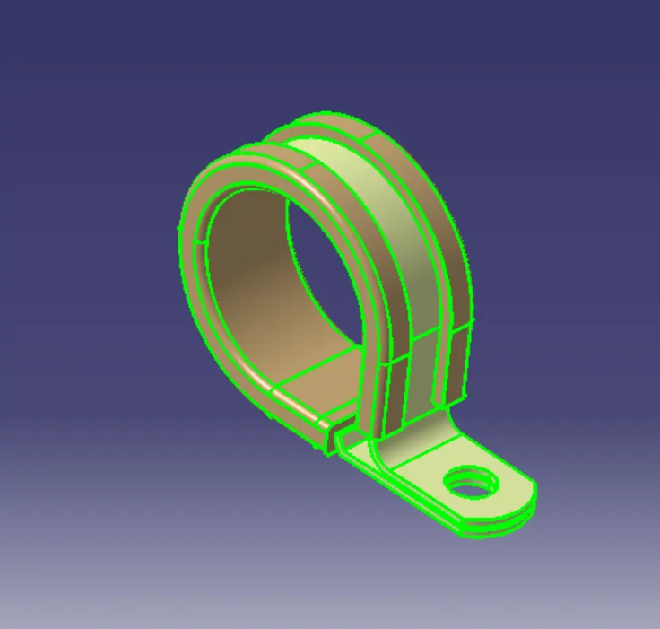
1. Create / download the 3D file:
In the mentioned assignment the P clamp 3 D part is provide in the question so we need not be bother to create the 3 D part
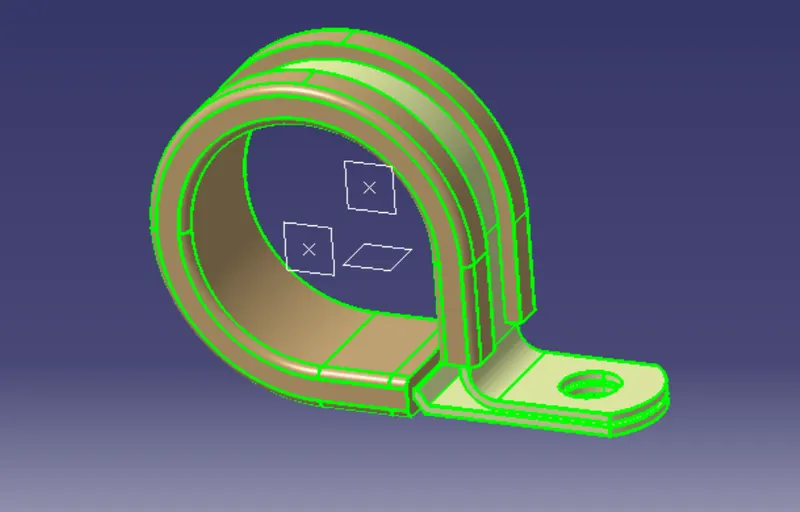
2.Create the required geometric reference elements:
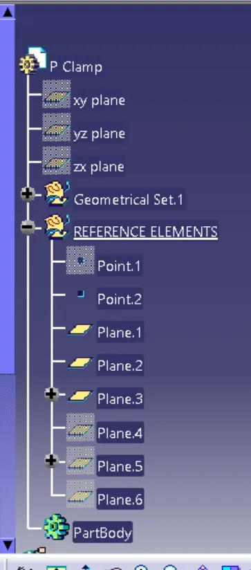
Now for the P clamp creae the reference planes and the points
It basically need to provide two entry points and the two exit points and the followig planes
- Entry plane
- Exit plane
- Base plane
3.Define the part as a support:
Now go to the electrical part design and define the cad part file as the support
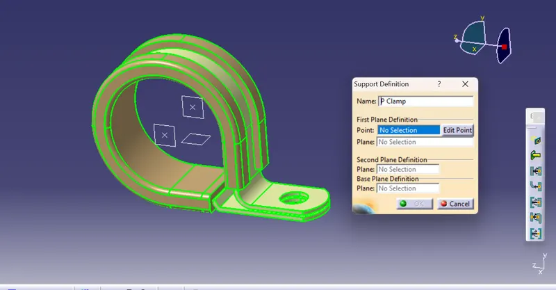
4. Define the entry point, entry plane, exit plane & the base plane:
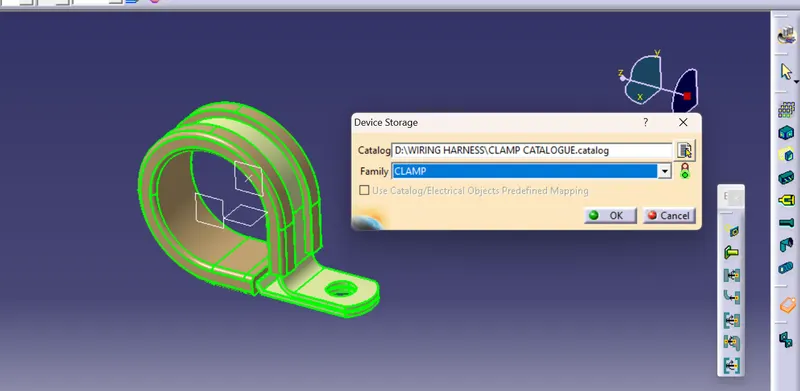
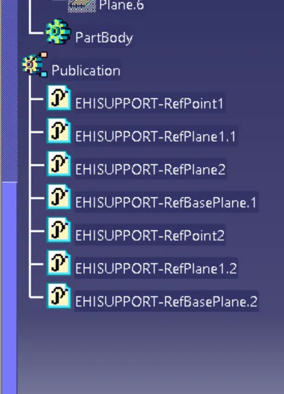
Now when we click on the support command a dialog box appears ask us to define the following reference planes and the points we create in the name of geometrical parameters
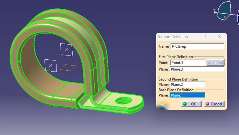
The other enrty should be need to provide as the p clamp has two entry points and the two exit points. For this we need to again define the part as the support and choose the other side of the P clamp as the entry point and the plane providing along with the exit point and the baser plae remains unaltered
Now create a catalogue to store the P clamp for the future use
The tree structure:
Question 02
Backshell
The procedure followed is
- Create / download the 3D part file
- Create the required geometric elements
- Define the part as the backshell
- Define th backshell connector connection point
- Define the bundle connection point
- Create / download the 3D part file
1.Create / download the 3D part file:
Download the backshell from the website called the TE. com
Basically backshell is a plastic molded part used at the wire entry or the bundle entry point of the connector either to provide the protection or tio increase the asthetic appearance
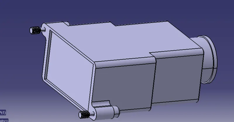
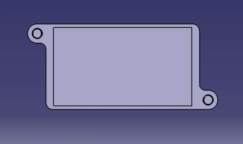
The connector mating side is
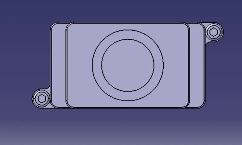
The bundle enrty side is
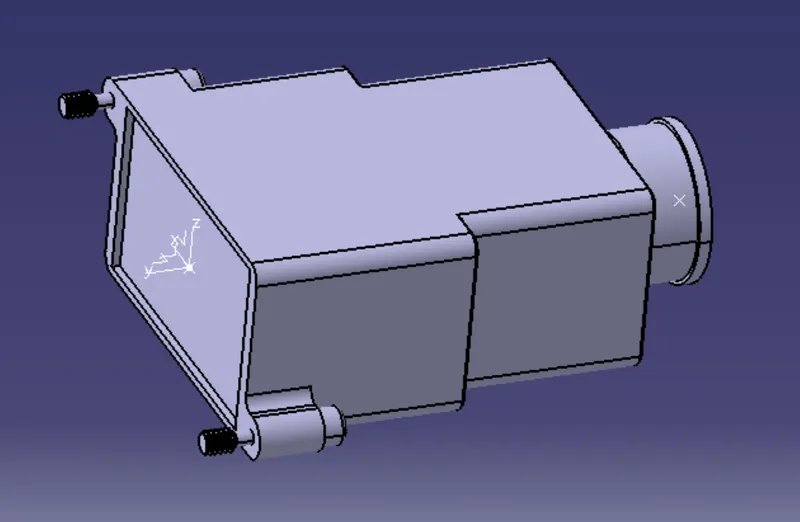
2. Now create the required geometric elements :
create the point and the axis system at the mating connector side and the point at the bundle entry side
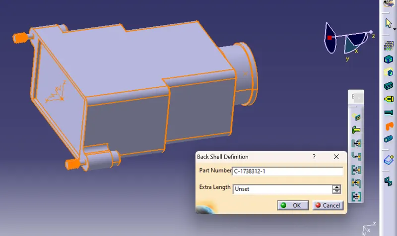
3.Define the part as the backshell:
4.Define the backshell connector connection point:
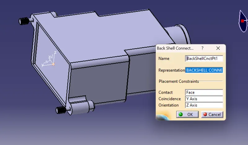
5.Define the bundle connection point:
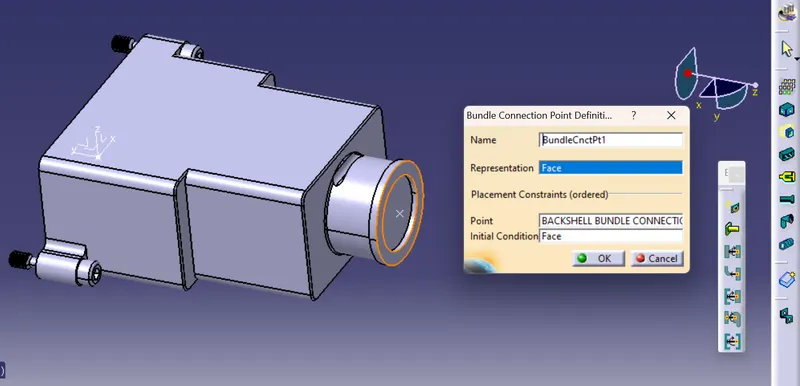
Now save the electrically defined CAT file
The tree structure is
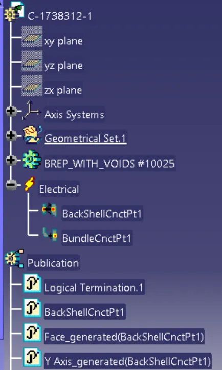
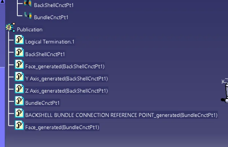
question 03:
Corrugated tubes/ cot tubes/ convolute tubes:.
These are the tubes which are generally emloyed to protect the wiring harness
Theprocedure followed is
- Open electrical part workbench
- Click on the protection part the dialogue box appears it shows the