Wiring harness routing & packaging Rules Week 3 Challenge
Q.1] The P Clamp was downloaded from the above website link. And then define it as Electrical support using Electrical Part design Workbench.
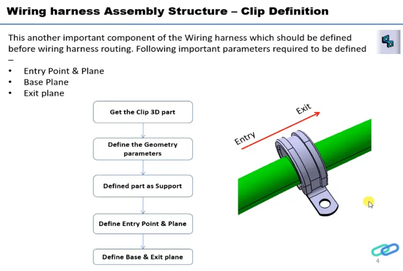
process:
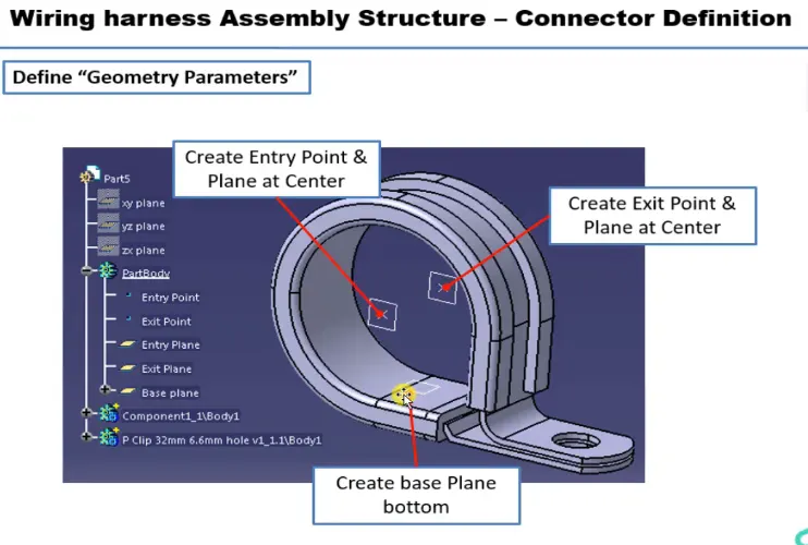
- Create two points one as entry and another as exit point.
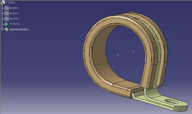
- create planes at two points and another at base.
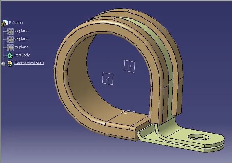
- Switch to Electric part design
- Click on support definition - select part - select entry point - select entry plane, exit and base plane.
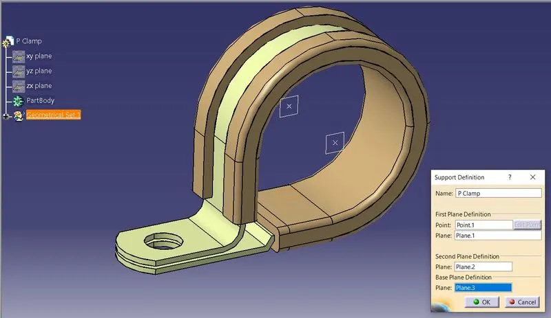
- Again Click on support definition - select part - select exit point - select exit plane and base plane as secondary plane is automatically taken.
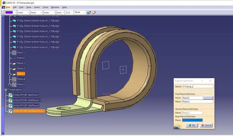
Q.2] First we want to download the following Back shell cad data & then define it as Electrical back shell using Electrical Part design Workbench.
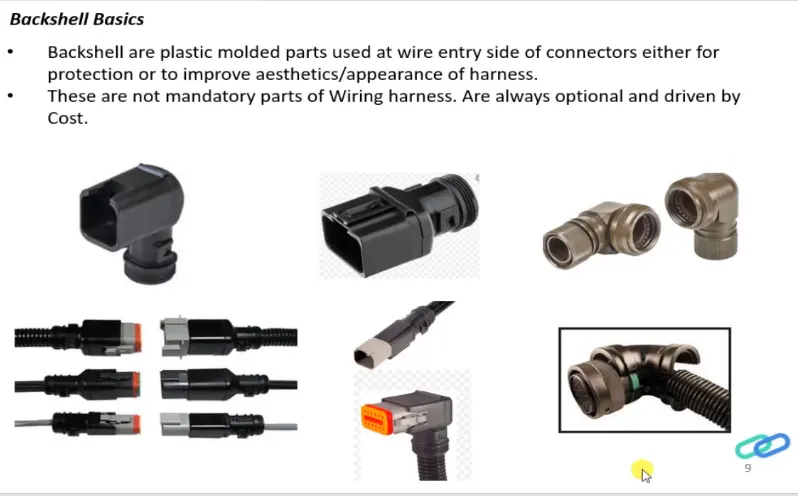
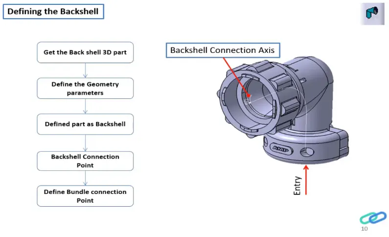
Process:
- Create Back shell entry point.
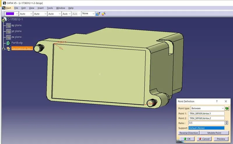
- Create axis system for back shell entry.
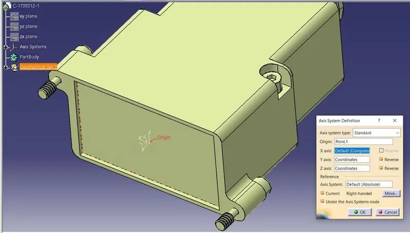
- Create bundle connection point.
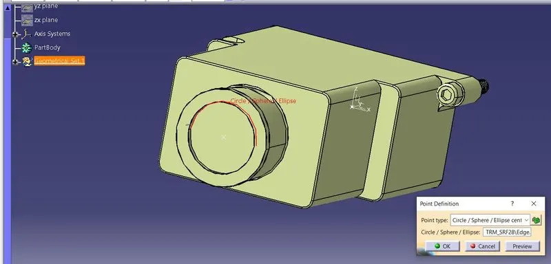
- Switch to Electrical part design.
- Define part electrically as back shell.
- Then define Back shell connection point.
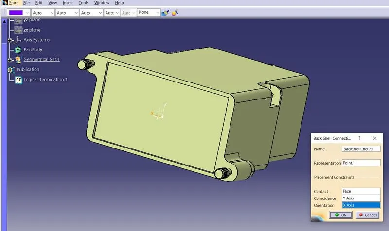
- Define bundle connection point.
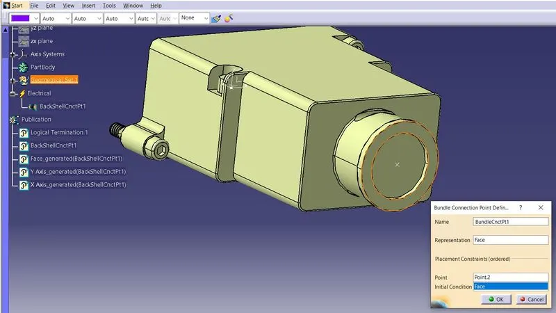
Q3. Create Following Corrugated tubes & Add them in Catalogue under “Slit COT” family.
|
Name |
ID (mm) |
OD (mm) |
Thickness (mm) |
|
15mm COT |
12 |
15 |
1.5 |
|
20mm COT |
17 |
20 |
1.5 |
|
35mm COT |
32 |
35 |
1.5 |
|
10mm COT |
7 |
10 |
1.5 |
|
5mm COT |
3 |
5 |
1 |
Catalogue Cretation:
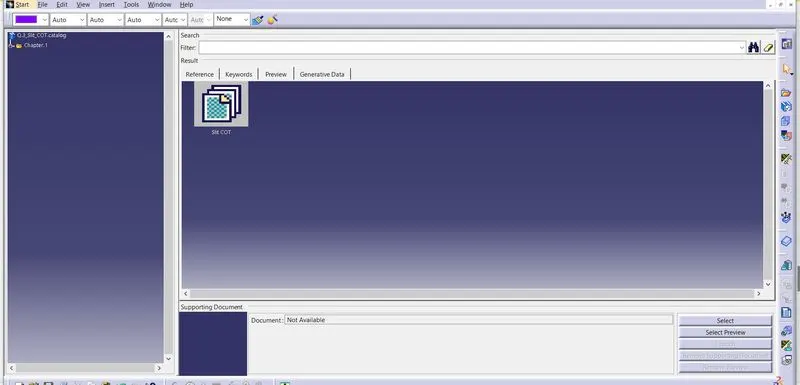
- new part - catalogue document - add family - give name - type - select Conduit - save.
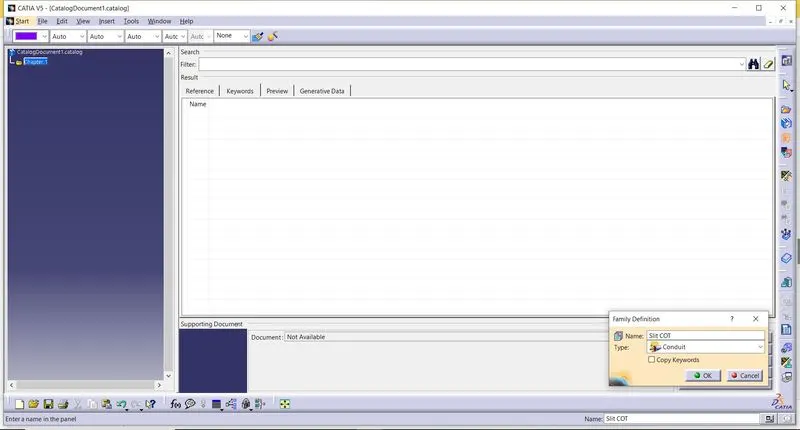
Process:
- Switch to Electrical part design
- Select Define protection Part
- Click on part (on file name in specification tree)
- Provide given parameters and bend radius.
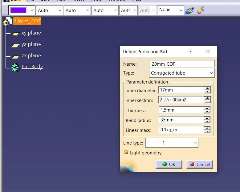
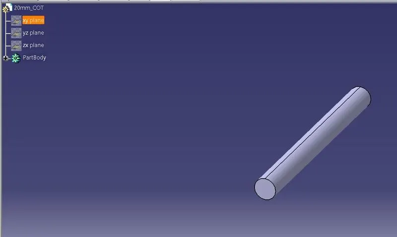
Repeat the same process for all the other parameters shown on the above.
And then open part to add catalogue - store device command - select catalogue - family - Slit_cot_tube - ok
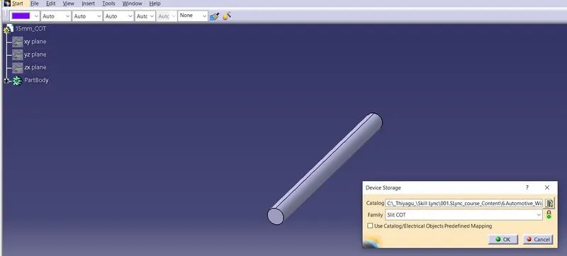
And finally all the Corrugated tubes are added to the Catalogue which has the Slit COT family.