Wiring harness routing & packaging Rules Week 3 Challenge
Report on giving the electrical defination to mechanical components and creation of corrugutted tubes.
Aim: to give the electrical defination to mechanical components after downloading them through the source and creating the corrugutted tubes on electrical part design then making the catolog for them.
Given data:
P Clamp,
Tyco 1738312-1 https://www.te.com/usa-en/product-1738312-1.html
For corrugutted tubes:
|
Name |
ID (mm) |
OD (mm) |
Thickness (mm) |
|
15mm COT |
12 |
15 |
1.5 |
|
20mm COT |
17 |
20 |
1.5 |
|
35mm COT |
32 |
35 |
1.5 |
|
10mm COT |
7 |
10 |
1.5 |
|
5mm COT |
3 |
5 |
1 |
Step 1: Start with downloading all source files required, after unziping the P clamp step file open it in catia and start working on it to define it ellectrically.
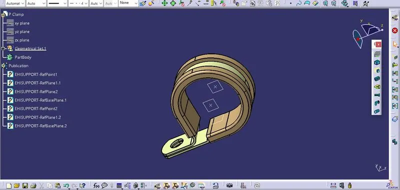
- First establish the geometric parameters by creating the entry and exit point then create plane through each point by taking reference as entry and exit surface of P clip.
- Now make the base plane by offset the base surface at 2 mm distance .
- Now define the Clamp by using "Define Electric support " command in elecrtic part design workbench, we define the two entries by defining each plane on side at a time in reference to base plane at each time, so our P clamp will get electrically defined by this way which is reprsented as shown below:
Step 2: Now download the Tyco 1738312-1 backshell from te.com and unzip the zipped file and open it on Catia V5, now open the file in part design to give the component the geometrical parameters.
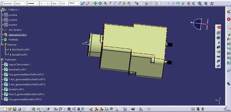
- Make the backshell connection point and bundle connection point on the front and back side of backshell surfaces, then create axis system on the backshell connection point by taking Y axis in direction of mating direction of backshell.
- Now define the part as backshell by using the same command in electrical part design.
- Then define backshell connection point by taking the backshell connection point as reference , face as the contact face where the the backshell and connector going to meet and coincidence axis as Y axis and oreintation axis as Z axis.
- And now define the bundle connection point by taking referance as the surface normal to the bundle point, initial condition as the same face.
- So in this way our Backshell is electrically defined now as show:
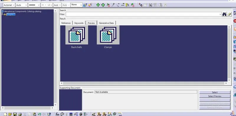
Step 3: Now make the catolog file for above made mechanical component, by creating new catalog file naming them as mechanical components catlog and adding two familes to it like backshells and clamp.
- Now add the respective component in the family by store device command in electric part design and save the catalog file which gonna look like this:
Step 4:Now Create a new part file and open the electric part design workbench click on "define protective part" command to create corrugutted tube as per reqiured dimension as mentioned in the question.
- On this window define the inner diameter, thickness and bend radius= 1.5*diameter of tube, since inner dia and thickness for each tube is given in the question and bend radius can be calculated from our side in this way we create all differents sizes of corruguted tubes and save them on by one by creating them on seprate part files.
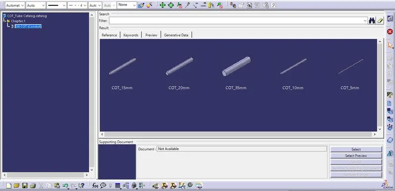
- Now create the catalog for these tubes by creating the new catalog file and addin the family naming " Slit COT" and save thsi catalog file first then add each COT tube by the store device command in the electrical part design by slecting the catalog and slecting the family name.
- So our catalog and Cot files in it will look like this: