Wiring harness routing & packaging Rules Week 3 Challenge
AIM : Define given clamp and back shell as an electrical support and electrical back shell and add their necessary properties using Electrical part design workbench in CATIA V5.
OBJECTIVE : Objective of this project is to first download the given file from the given link and define all of them as an electrical support and back shell and give all the required electrical properties to them using the electrical part design workbench in CATIA V5.
GIVEN DATA :
- P clamp
- Tyco 1738312-1 back shell
- Corrugated tube with dimensions
(Q1 ) P CLAMP
These are the following steps required to do this project.
- Import the 3D cad file in catia v5
- Create the required geometrical parameter for Clamp
- Define point (Entry point and Exit point)
- Define plane (Entry plane, exit plane and base plane)
- Select the electrical part design workbench
- Define as support (For entry and exit)
Figure 1: Defining the Geometrical parameter for the P-clamp
- Point Definition
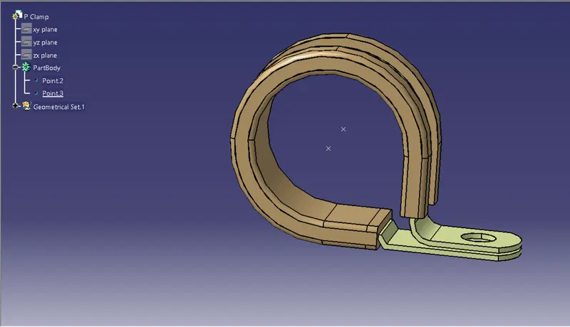
Figure 2: Defining the Geometrical parameter for the P-clamp
- Plane definition
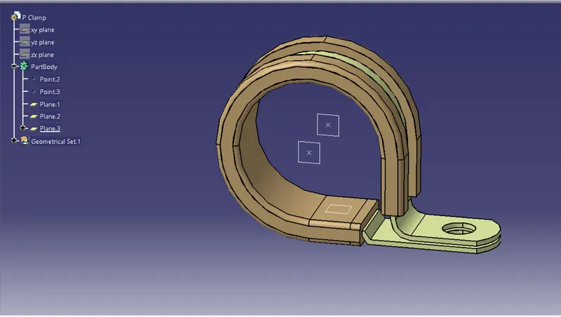
Figure 3: Defining the clamp as electrical support
- Entry Support definition
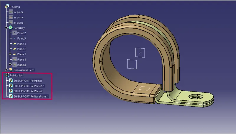
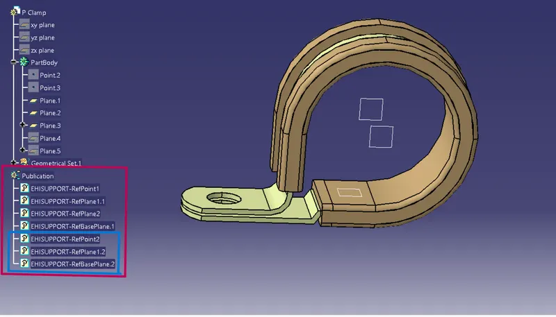
Figure 4: Defining the clamp as electrical support
- Exit Support definition
(Q2) Back Shell - Tyco 1738312-1
These are the following steps required to do this project.
- Import the 3D cad file in catia v5
- Create the required geometrical parameter for Clamp
- Define point
- Define Axis system
- Select the electrical part design workbench
- Define as back shell
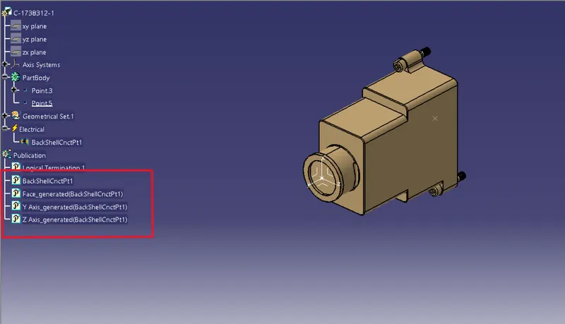
- Define as back shell connection point
Figure 1: Defining the geometrical parameter for the Tyco back shell
- Point definition
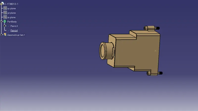
Figure 2: Defining the geometrical parameter for the Tyco back shell
- Define Axis sytem
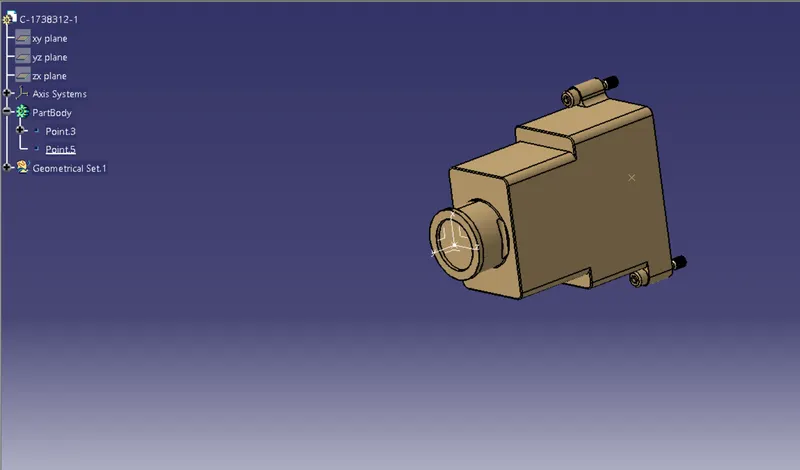
Figure 3: Defining the tyco 1738312-2 shell as a backshell
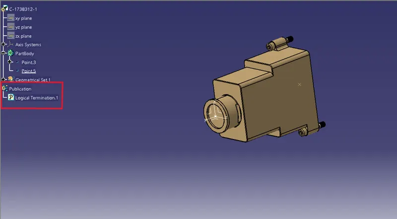
Figure 4: Defining the tyco 1738312-2 shell as a backshell Connection point
(Q3) Corrugated tube and their catalogue
|
Name |
ID (mm) |
OD (mm) |
Thickness (mm) |
|
15mm COT |
12 |
15 |
1.5 |
|
20mm COT |
17 |
20 |
1.5 |
|
35mm COT |
32 |
35 |
1.5 |
|
10mm COT |
7 |
10 |
1.5 |
|
5mm COT |
3 |
5 |
1 |
These are the following steps to do this project:
- create a new part with their name
- Create covering 3D part
- Define catalogue for covering
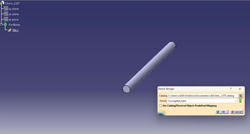
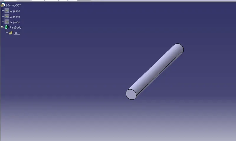
- Add new part in catalogue
- Apply covering in harness bundle from catalogue
Corrugated tube with dimension
15mm COT ( ID = 12 mm, OD= 15mm, thickness = 1.5mm)
Figure 1: 15mm_COT Corrugated tube
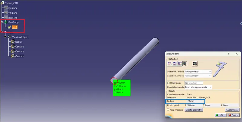
Figure 2: Adding 15mm corrugated tubes in catalogue
Corrugated tube with dimension
20mm COT ( ID = 17 mm, OD= 20mm, thickness = 1.5mm)
Figure 1: 20mm_COT Corrugated tube
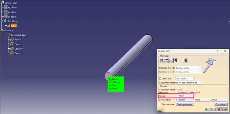
Figure 2: Adding 20mm corrugated tubes in catalogue
Corrugated tube with dimension
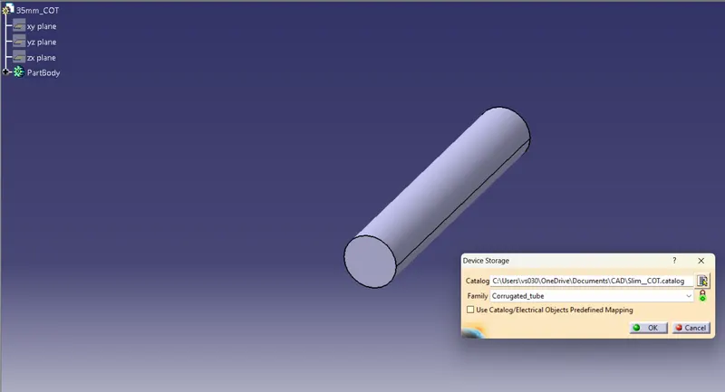
35mm COT ( ID = 32 mm, OD= 35mm, thickness = 1.5mm)
Figure 1: 35mm_COT Corrugated tube
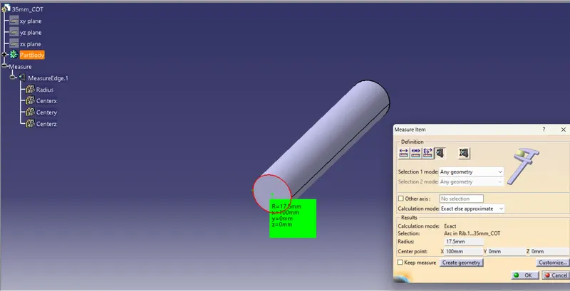
Figure 2: Adding 35mm corrugated tubes in catalogue
Corrugated tube with dimension
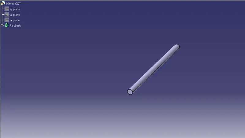
10mm COT ( ID = 7 mm, OD= 10mm, thickness = 1.5mm)
Figure 1: 10mm_COT Corrugated tube
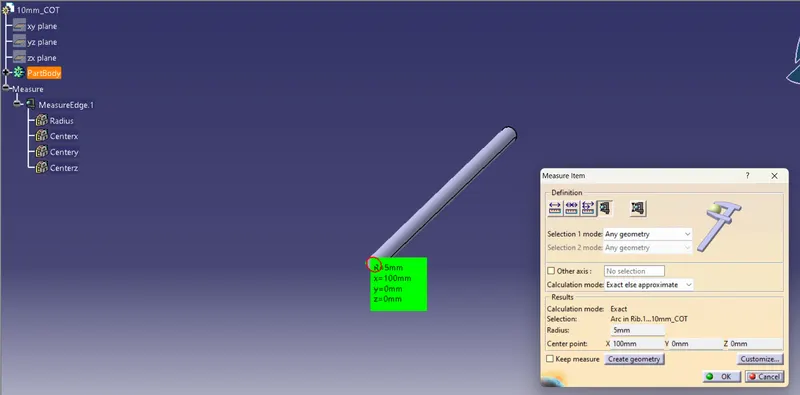
Figure 2: Adding 10mm corrugated tubes in catalogue
Corrugated tube with dimension
5mm COT ( ID = 3 mm, OD= 5mm, thickness = 1mm)
Figure 1: 5mm_COT Corrugated tube
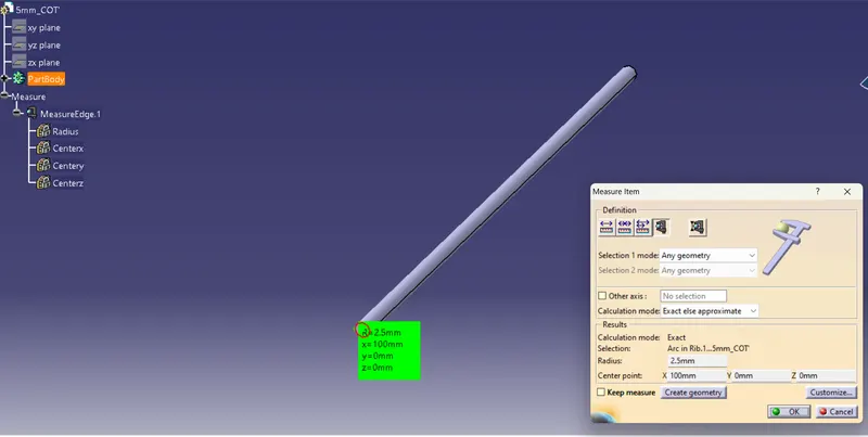
Figure 2: Adding 5mm corrugated tubes in catalogue
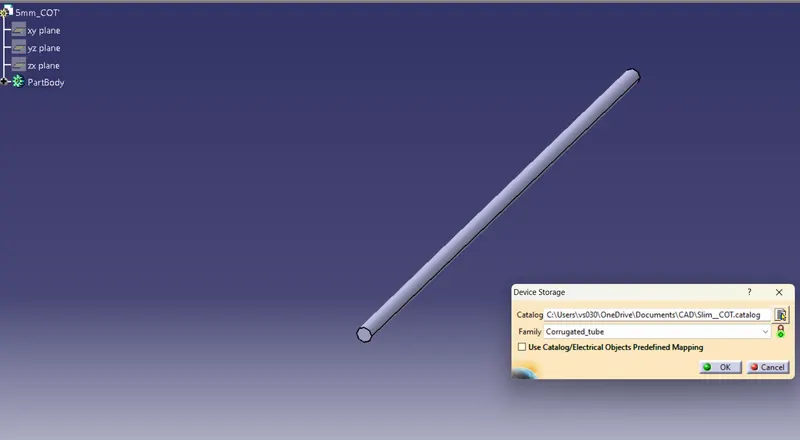
CONCLUSION : P Clamp and the TYCO- 1738312-1 were defined as an electrical clamp and electrical back shell respectively. All the necessary electrical and geometrical properties were given to the parts. And define Corrugated tubes and add these into catalogue under "Slim_COT" file.