Wiring harness routing & packaging Rules Week 3 Challenge
P clamp
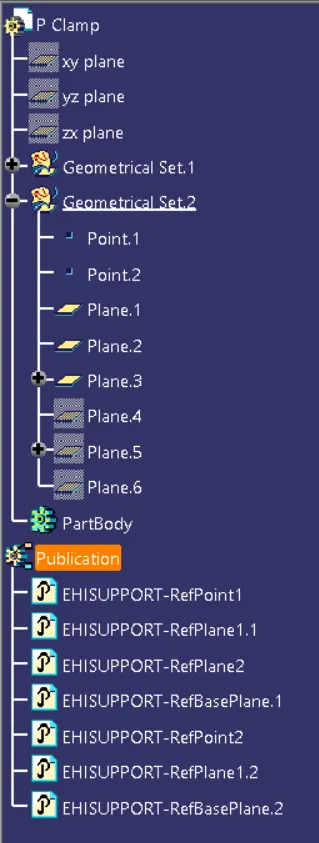
- Create Geometrical parameters required for the Support component, which are 2 points and 3 planes.
- Define the P Clamp as Support part in Electrical workbench, by mentioning the
- Entry point
- Entry plane
- Exit plane
- Base plane.
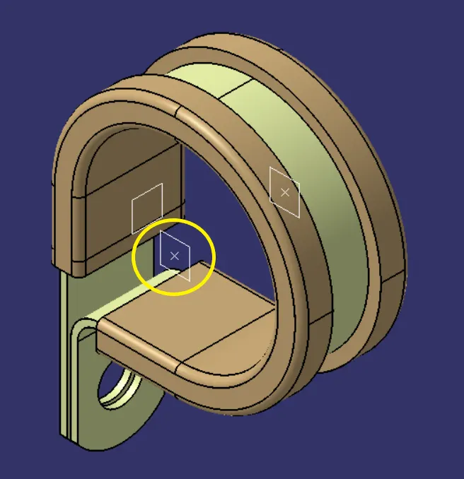
Exit plane ( The second entry point &plane )
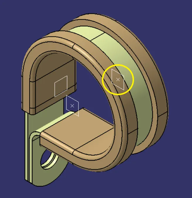
Base plane
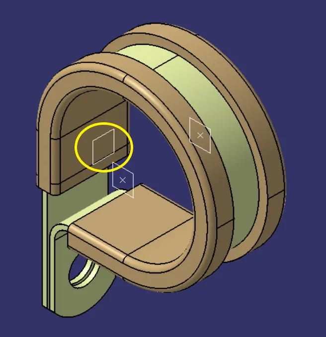
Electrical properties
Back shell - Tyco 1738312-1 ( C-1738312-1 )
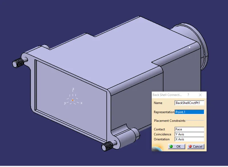
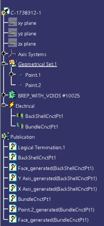
- Create Geometrical parameters required for the Back shell, which are 2 points and 1 Axis system.
- Define the part as Back shell in Electrical workbench.
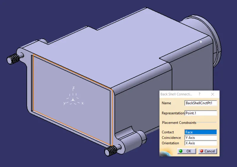
- Define the Back shell Connection point with ref. face and axes.
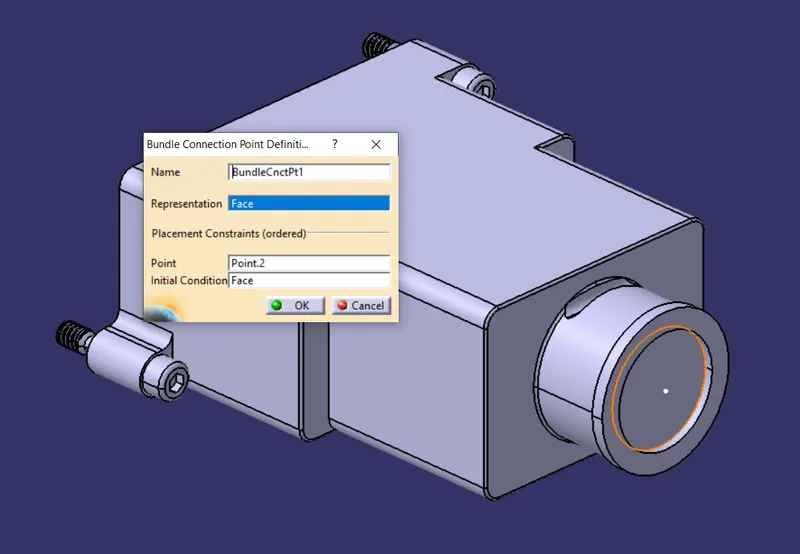
- Define Bundle connection point.
Back shell Connection point - Ref point & Ref axis system
Back shell Connection point - Ref face
Bundle connection point
Electrical properties
Cot Tubes
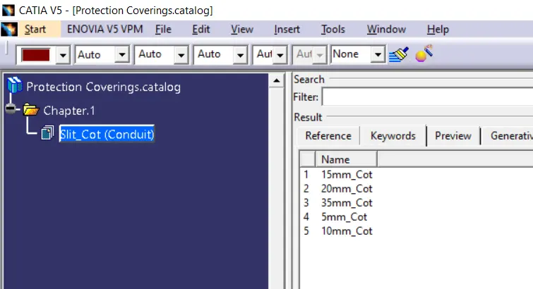
- Crete a Catologue document for Cot tubes.
- Create an Electrical part, Define the part as Protection part.
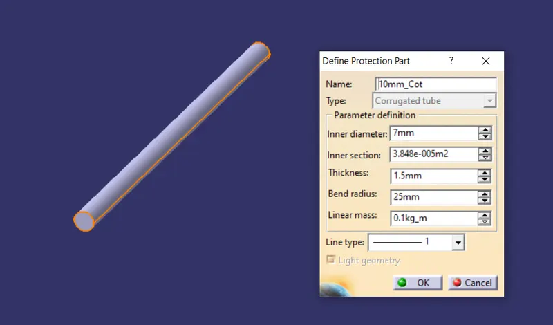
- Enter the given parameters to define the Protection part as Corrugated tube.
- Follow the procedure for the below individual parts and save each of them in the created catalogue uder Slit cot family.
|
Name |
ID (mm) |
OD (mm) |
Thickness (mm) |
|
15mm COT |
12 |
15 |
1.5 |
|
20mm COT |
17 |
20 |
1.5 |
|
35mm COT |
32 |
35 |
1.5 |
|
10mm COT |
7 |
10 |
1.5 |
|
5mm COT |
3 |
5 |
1 |
Cot tube definition example ( 10mm Cot )
Cot tubes Catalogue