Wiring harness routing & packaging Rules Week 3 Challenge
WIRING HARNESS ROUTING AND PACKAGING RULES
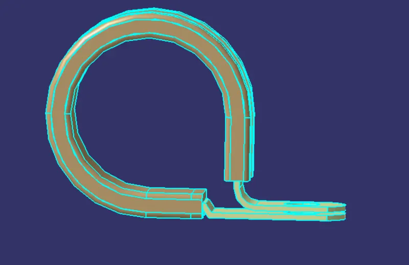
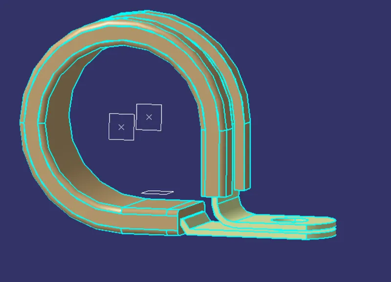
- DEFINE THE CLIP AS ELECTRICAL SUPPORT USING ELECTRICAL PART DESIGN WORKBENCH
STEPS
- Create two points on the two sides of the p clamp as shown below
- creates two planes on that point and one at the base
- Switch to electrical part design workbench
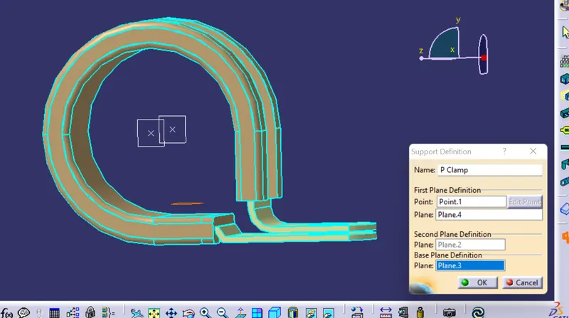
- select support definition and select the points and plane to make 2 entry and exit respectively as shown below.
- finally the clip is defined as electrical support.
- DEFINE THE BACKSHELL AS ELECTRICAL BACKSHELL USING ELECTRICAL PART DESIGN WORK BENCH
STEPS
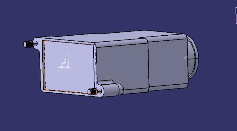
- Create entry point and exit point for the backshell
- create axis system for the backshell connection point
- Switch to electrial part design workbench
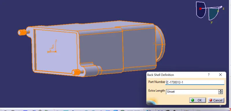
- define the part as backshell electrically
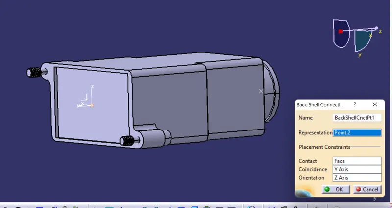
- then define the backshell connection point
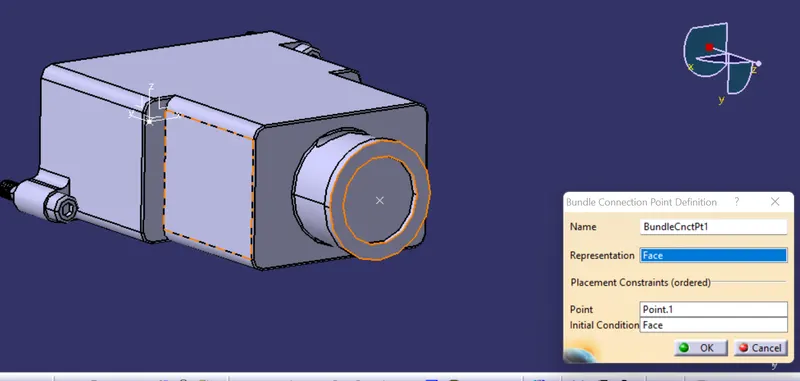
- define bundle connection point.
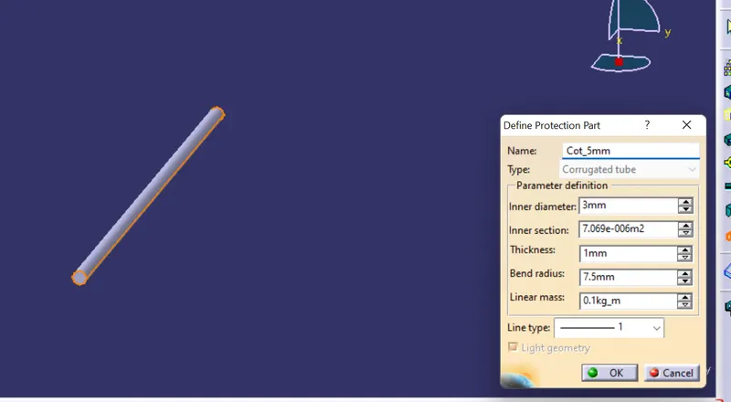
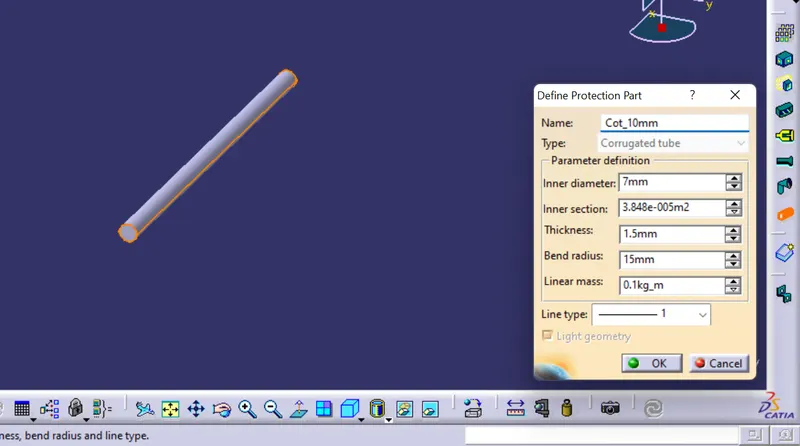
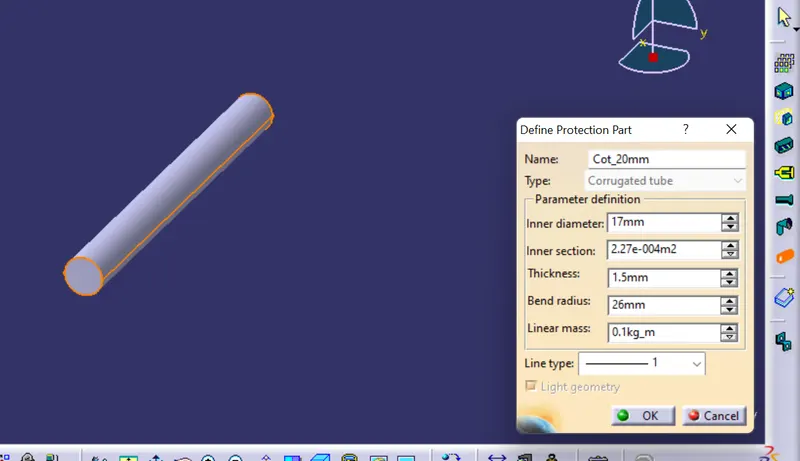
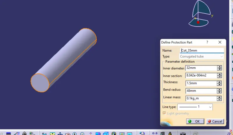
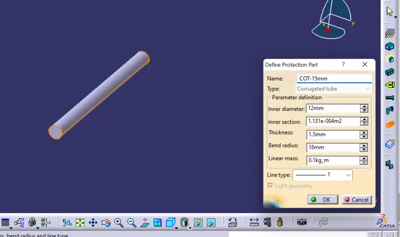
- CREATE COT TUBES AND ADD THEM IN CATALOGUE
|
Name |
ID (mm) |
OD (mm) |
Thickness (mm) |
|
15mm_ COT |
12 |
15 |
1.5 |
|
20mm _COT |
17 |
20 |
1.5 |
|
35mm_ COT |
32 |
35 |
1.5 |
|
10mm_ COT |
7 |
10 |
1.5 |
|
5mm_ COT |
3 |
5 |
1 |
STEPS
- Switch to electrical part design
- Create new part design and select define protection part and select the part body
- give the parameters required
- Add the created cot tubes to a catalogue named SLIT COT TUBES,