Wiring harness routing & packaging Rules Week 3 Challenge
Week 3- Wiring harness routing & packaging Rules Challenge
1. Introduction-: In this challenge we will be working on the support equipments, protection equipments & backshells. We will be defining them as electrical support, backshell & adding them in the catalogue for future reference.
2. Modelling & Defining of Part Body in Electrical Part Workbench-:
a. P-Clamp-:
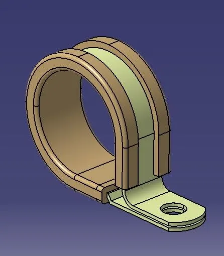
Procedure-:
1. Download the 3D Cad data and save it as .CATpart in the desired location.
2. Define the Entry & Exit points for bundle and their respective planes as illustrated below by taking the reference of the 3D Cad data in the Part Workbench.
3. Define the base plane for the P-clamp using the reference from 3D cad data as illustrated below.
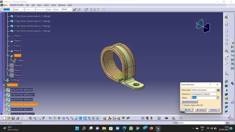
4. Now define the P-Clamp part body as Support Part in Electrical part workbench as illustrated below.
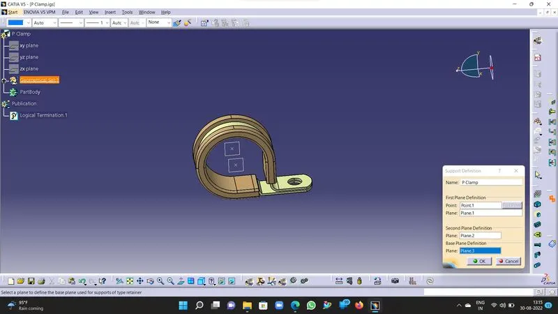
5. Note their will be two entry points & two exit points in the P-clamp so define the support part twice using the same command.
6. Now the part is defined as Electrical Support part, save the Part file for future reference & store it in catalogue by using Store device command in the Electrical part workbench.
b. Backshell-:
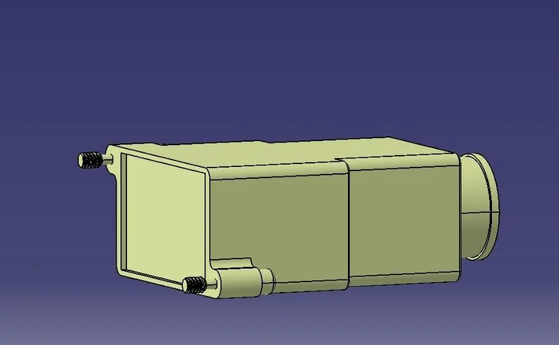
Procedure-:
1. Download the 3D cad data and save it as .CATpart in the desired location.
2. Now define the Backshell connection point & axis by taking the reference from 3D cad data such that it satisfies the mating condition of the backshell and the connector. The Y axis should face the mating direction and other axis X & Z should face similar orientation as defined on the mating part.
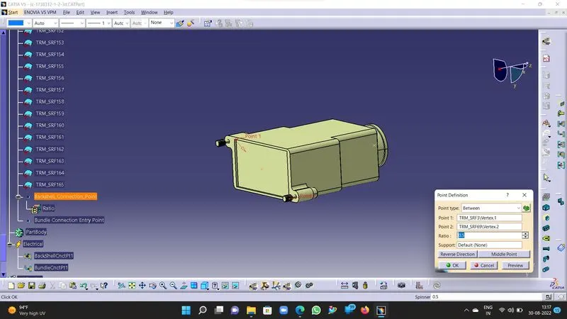
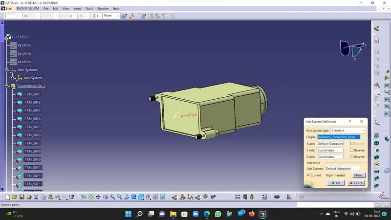
3. Now define the bundel connection point by taking the reference from 3D part model.
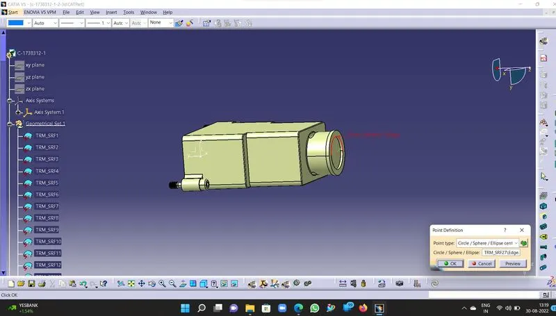
4. Switch to Electrical part workbench and define the backshell as Electrical backshell using the "Define Backshell" command in the workbench, its properties will get stored in publications.
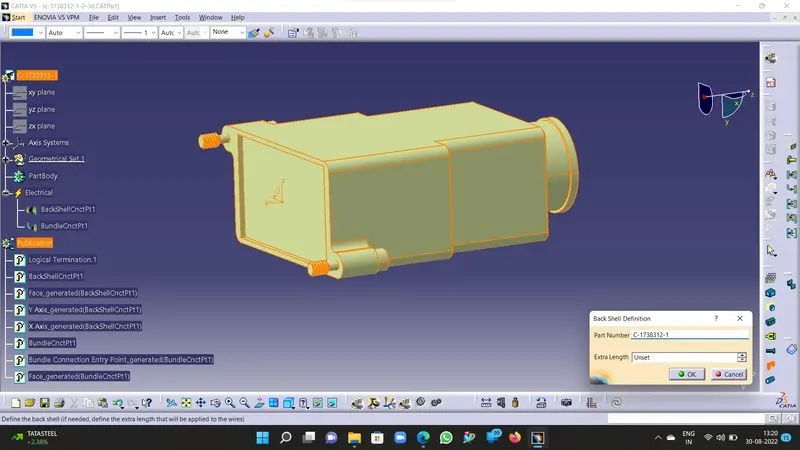
5. Now define the Backshell connection points using the reference of the points & axis defined on the backshell as connection points as illustrated below.
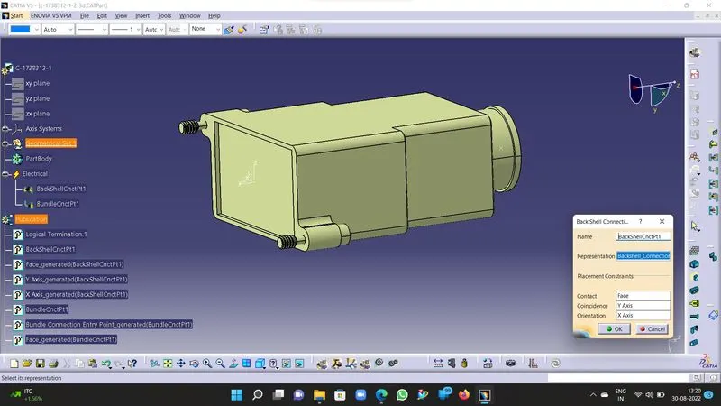
6. Define the Bundel connection point as illustrated below.
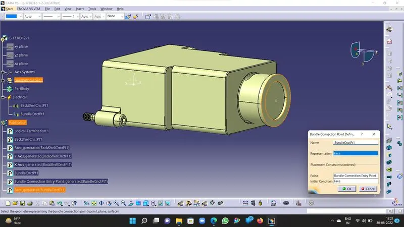
7. Now the part model is defined as Electrical Backshell save the part in the desired location.
8. We can store the part in the respective catalogue for future reference with part model number.
c. Corrugated Tubes-:
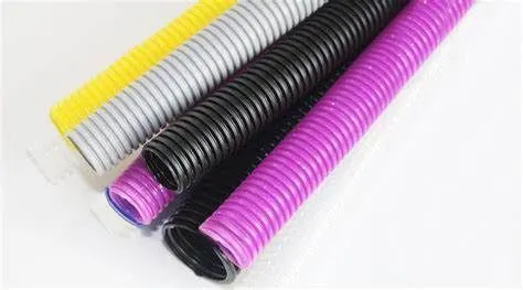
Procedure-:
1. Open the Catia V5 and start the new Part model by defining it with the part number such as for corrugated tubes 5 mm it can be COT_5mm.
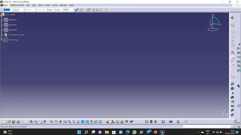
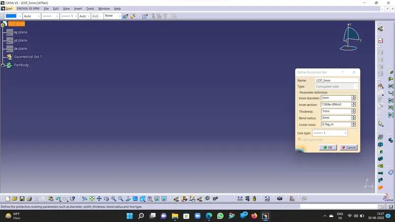
2. Now switch to the Electrical part workbench and define the Cot_5mm part model as Electrical Protection part using the "Define Protection Part" command as illustrated below. Define the parameters and click on ok.
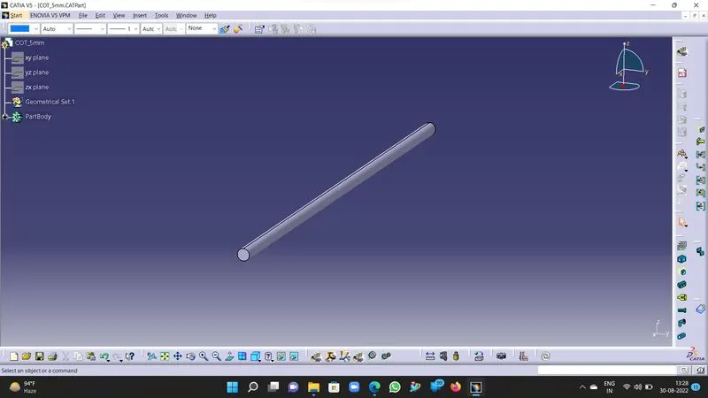
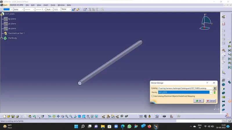
3. Now a 3D part model will be defined as protection part in the electrical workbench, save the part model and store it in catalogue for future reference under the family "SLIT Cot" as illustrated below.
4. Repeat the steps for each Cot_Tube part model.