Fender Design Challenge
FRONT FENDER PROJECT
Introduction-:
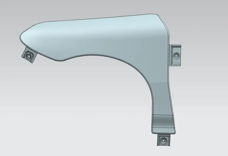
Fender is the sheet metal part that frames or cover the wheel well. The Fender is another important part/component of BIW body. Fender protects the pedestrian and engine from debris, rocks, mud, liquid. During the motion the wheels pickup the rocks, debris or mud from the road surface and tends to throw outwards which can get impacted on engine as well as pedestrians. The fenders according to design perspective are classified into two types – full bumper type, half bumper type. Now a days half bumper type is considered for designing the fender as this approach leads to reduce scrap wastage and increases manufacturing capacity. The different type of mountings in a fender are-
- Bumper.
- A-Pillar.
- Baffle.
- Sill.
- Drip.
Objective-:
The main objective of this project is to learn the design requirements for fender, functional requirements, drip area mounting and its significance, baffle and OVRM mounting, important standard regulations, wheel arch requirements, frontal crash regulations. The overall learning of the project is to learn and design the fender and its components as per the real-life conditions. The project includes challenges such as the different mountings and its appearance. We have been provided with Class A surface in reference to which we need to design the different mountings such as – A-pillar mounting, bumper mounting, sill mounting, baffle mounting, and drip area mounting keeping in mind its aesthetic appearance.
A. Design Requirements-: The design requirements for the fender part are mostly in regard to the regulations and standards. The fender is to be designed taking into consideration the hood, bumper, A-pillar, engine mounting/drip area, wheel arch area. The Fender design should be aesthetically appearing. Some of the regulations and standards to be kept in mind while designing the fender part are –
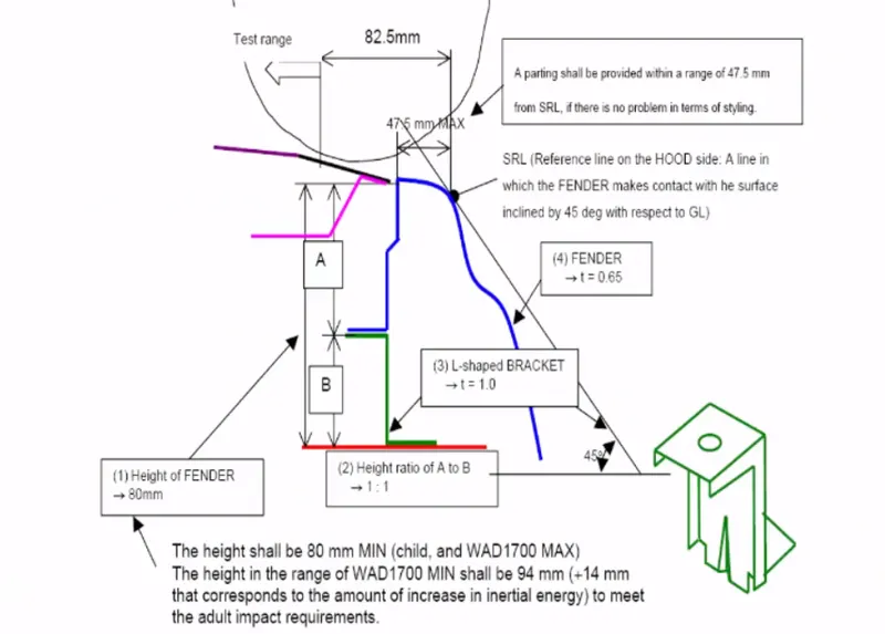
- Fender Pedestrian safety-: In fender pedestrian safety standards the dimensions and mountings play a major role such as the distance between the drip area and extreme point of hood should be not more than 50 mm. This distance plays a significance in aesthetic appearance as well as pedestrian safety due to the wrap around distance and front collision. The total height of the child part from drip area to the engine room should not be more than 80mm – 90mm, if it is more than 90mm it should result in impact energy during front collision.
- Wheel Arch requirements-: The wheel arch requirement is the requirement that states the clearance between the wheel and fender from the centre of the wheel. The Wheel arch varies from region to region such as stated below. The Wheel arch study is important for pedestrian safety and it varies from region to region due to the different road conditions. If a car is to be designed for multiple regions, so this study plays a major role in designing of the fender. The different region regulations are-:
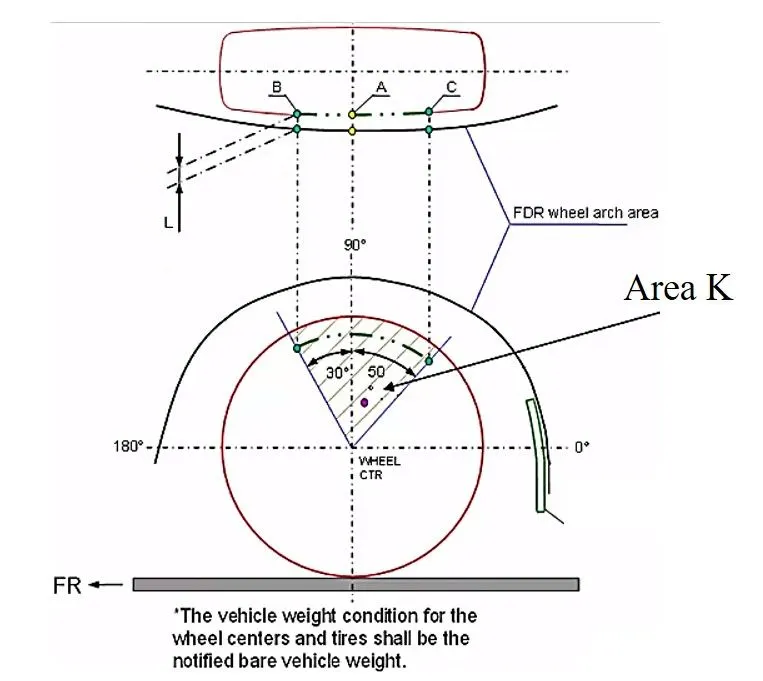
1. Japan Regulations-: According to Japan regulations lines are drawn from centre of tyre at 0°, 30°, 50°, 180°. The 50° line is drawn at the right side of the wheel and 30° is drawn on to the left side. These lines are projected and after projection the clearance “a” should be 5mm not more than that. These regulations are set according to the road conditions in Japan by the national government.
2. European Regulations-: According to European regulations lines are drawn from centre of tyre at 0°, 30°, 50°, 180°. The 50° line is drawn at the right side of the wheel and 30° is drawn on to the left side. Apart from these lines a line is drawn 150mm above the 0° line and the centre line is also drawn between 50° line and 150mm above line. These lines are projected and after projection the clearance “a” should be 10mm not more than that. These regulations are set according to the road conditions in Japan by the national government.
3. U.S. Regulations-: According to U.S. regulations lines are drawn from centre of tyre from -20° to 180° at each 10° interval. The 50° line is drawn at the right side of the wheel and 30° is drawn on to the left side. These lines are projected and after projection the clearance “a” should be 5mm not more than that. These regulations are set according to the road conditions in U.S. by the national government.
B. Functional Requirements-: The functional requirements for the fender are the mountings and the pedestrian safety. The pedestrian safety regulations and standards have been mentioned above. Now we will list out the different mountings and their significances –
1. Drip Mounting-: The drip mounting is the mounting near the engine compartment. This is the most important mounting as it is exposed to the vibrations and impacts from the suspensions. The drip mounting is designed using the master section provided to us. According to the section we need to keep certain dimensions in consideration which when exceeded will lead to drastic impacts in manufacturing of part. The master sketch is attached below for reference -
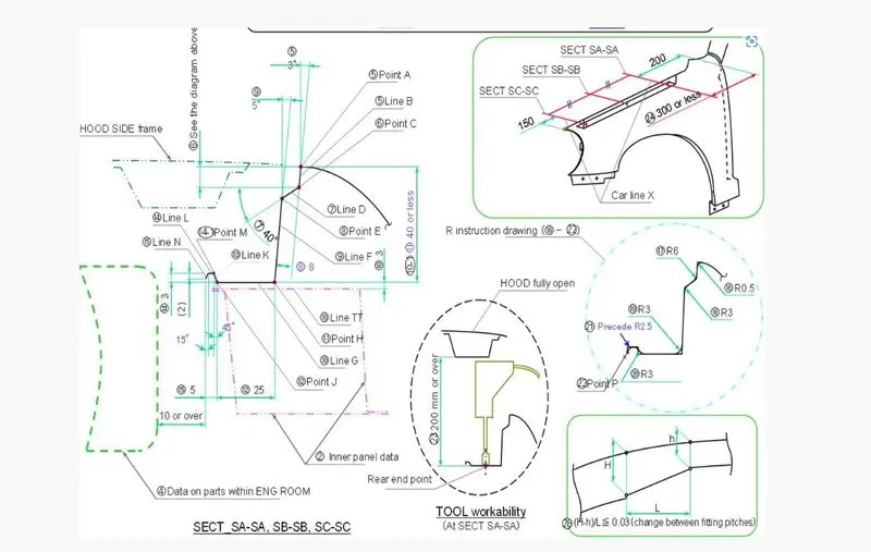
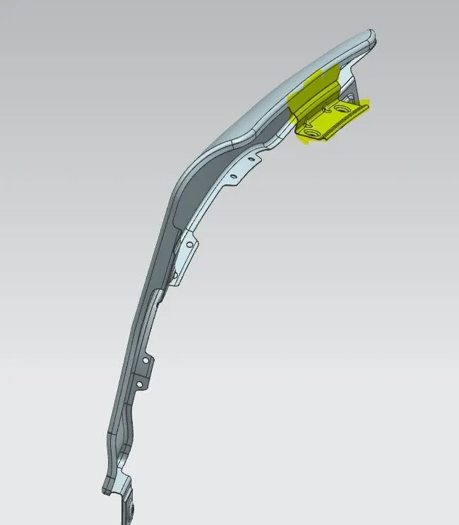
Shaded section is the Drip mounting area
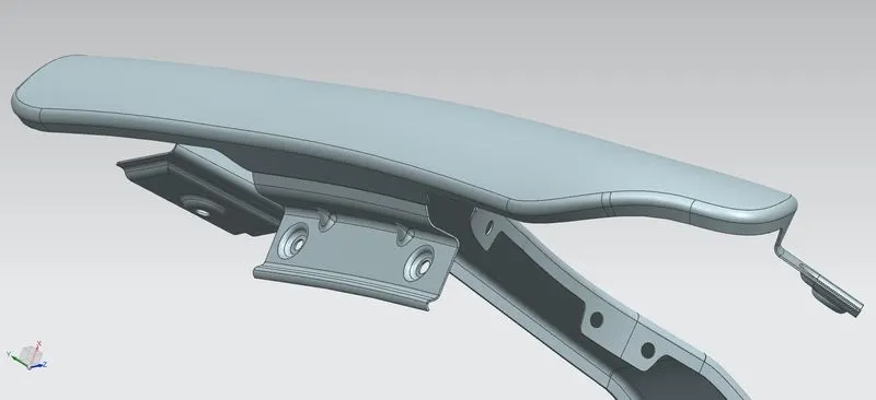
2. A-Pillar Mounting-: A-pillar mounting is the mounting which is also called side door mounting. This mounting is designed in consideration to the side door and cowl mounting. The A-pillar mounting sometimes provided with baffles to provide better NVH. As the baffle provide damping to the mounting.
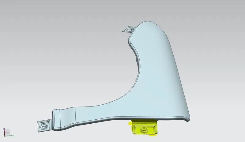
Shaded Section is the A-Pillar Mounting
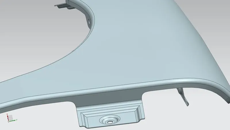
3. Sill Mounting-: The sill mounting is the bottom most mounting that is mounted on to the chassis or the body of the automobile. The sill mounting is designed in consideration to the baffle mounting and A-pillar mounting.
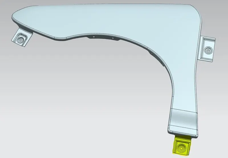
Shaded section is the Sill mounting
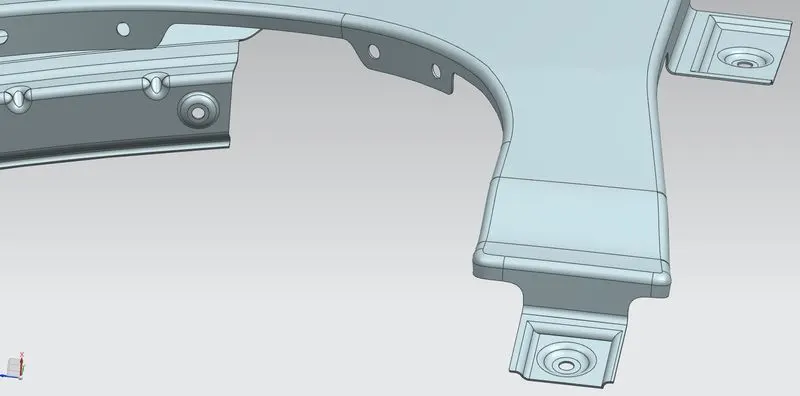
4. Bumper Mounting-: The bumper mounting or the bonnet mounting is the frontmost mounting of the fender which is mounted on the bumper or the bonnet region of car.
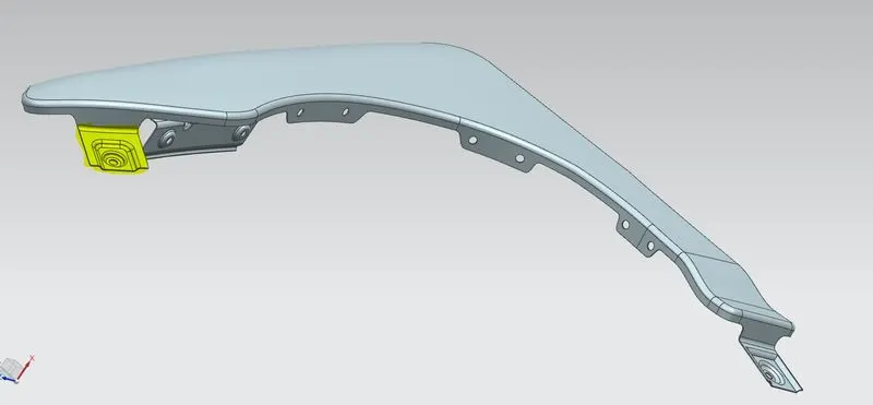
Shaded Section is the Bumper mounting
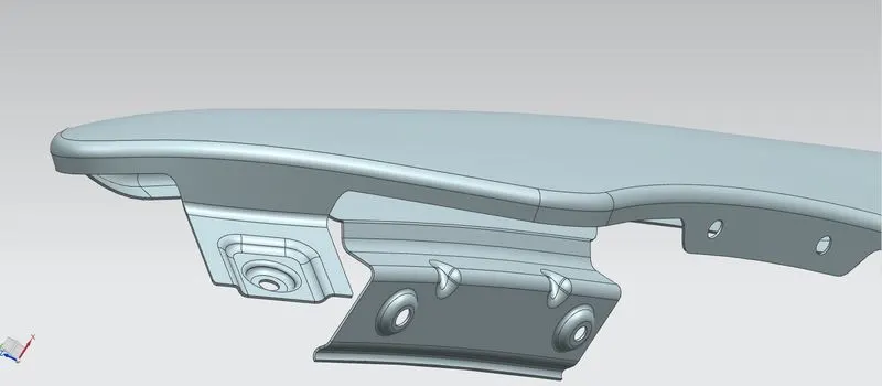
5. Baffle/Mudguard mounting-: The baffle mounting is the mudguard/wheel cap mounting which protects the pedestrian and engine from stones, debris and other foreign particles that can damage and leave drastic impact. The baffle mounting is designed taking into consideration wheel position and sill mounting.
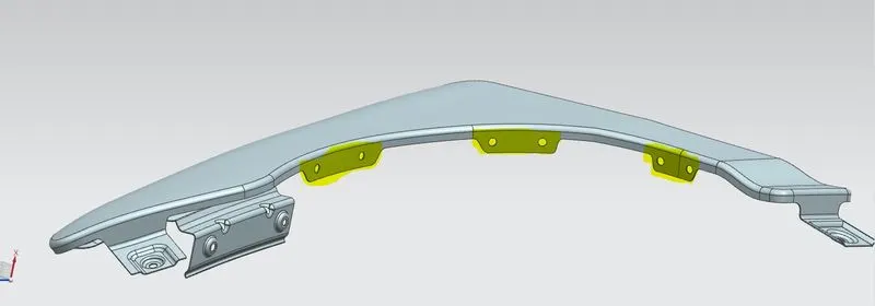
Shaded Section is the Baffel/Mudguard mounting
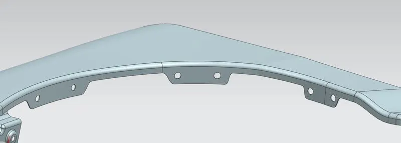
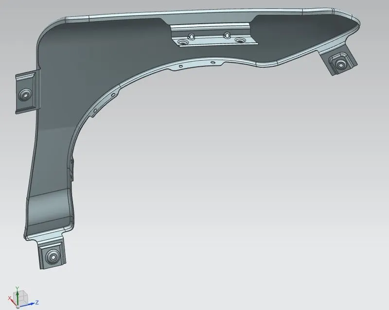
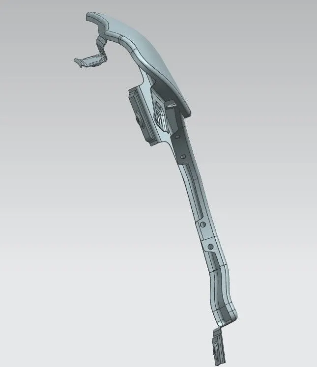
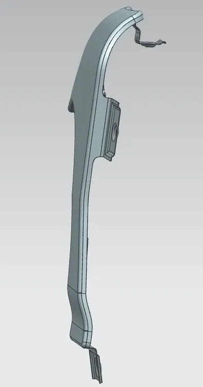
Some of the views of fender is attached below for your reference –
Conclusion-: The overall learning from this project is the design regulations and safety regulations to be considered for designing this part. This project gives us brief insights on industry level designs, their analysis for manufacturing processes, safety regulations.