Radar Mast & Final Assembly of Yacht
Challenge -: Radar Mast Modelling & Assembly of Yacht Model.
1. RADAR MAST-:
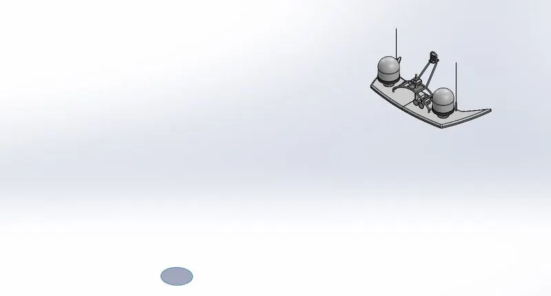
a. Isometric View-:
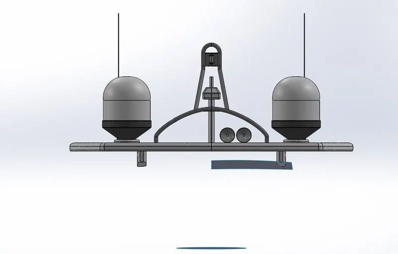
b. Front View-:
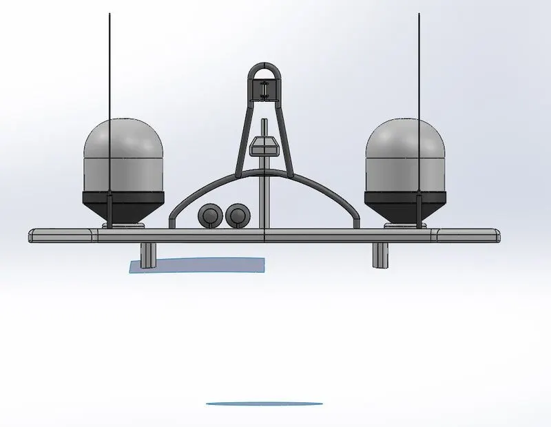
c. Back View-:
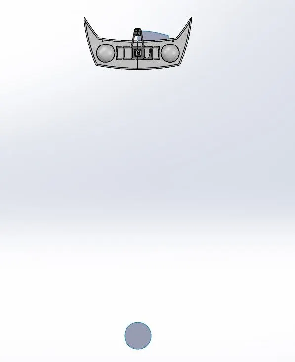
d. Top View-:
e. Bottom View-:
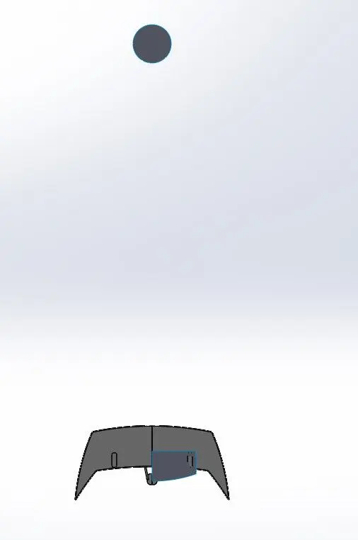
f. Left View-:
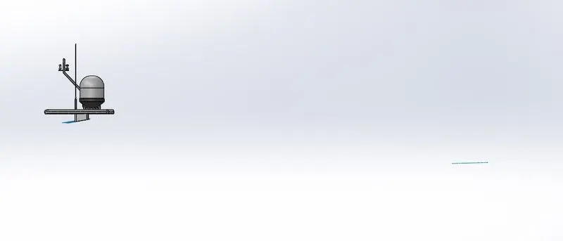
g. Right View-:
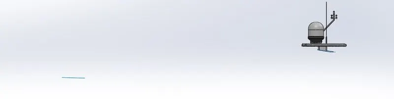
h. Feature Tree--:
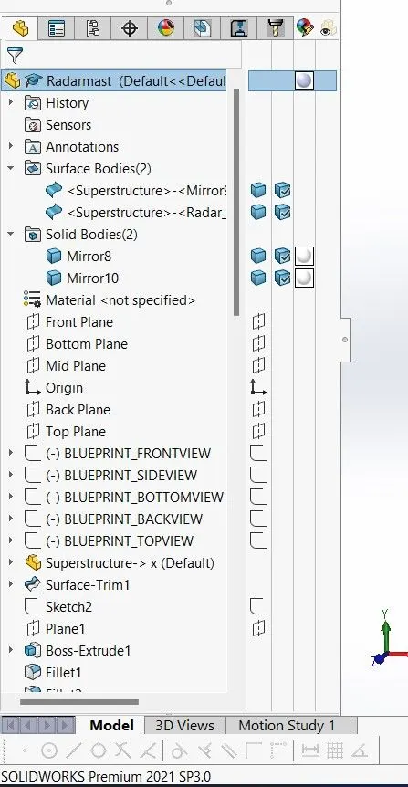
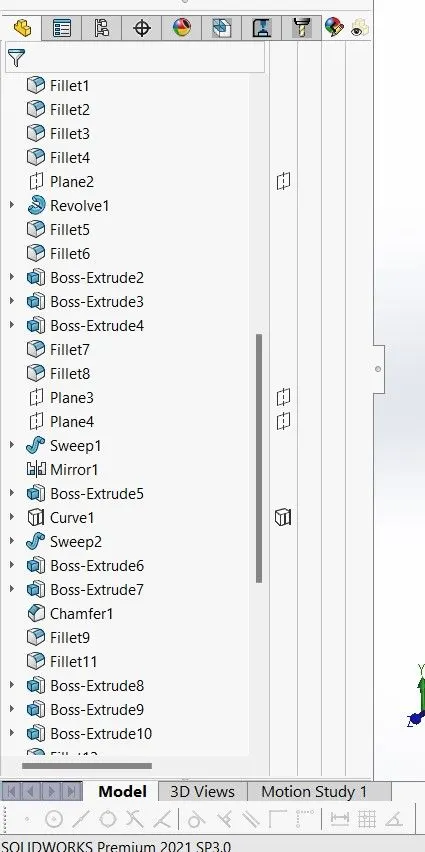
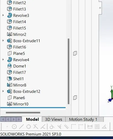
2. Assembly of Yacht Model
PROJECT REPORT OF YACHT ASSEMBLY
Yacht Design
Objective-: The objective behind design of this project is to understand the concept of sketching, modelling & assembly of Yacht in solid works using sketch tools, features, appearances, defining mates, using relations, creation of reference planes, using curves tool, split lines, split tool & surfaces tools.
Introduction-:
Understandings & implementation of the following tools & features is the primary objective of this project. Implementation of these tools & features gives a vast exposure on the concepts for giving your imagination a proper well-defined sketch & modelling it into a 3D model. The following command & features are-:
- Boss Extrude.
- Cut Extrude.
- Surface Loft.
- Surface Fill.
- Project Curve.
- Split Line.
- Delete Face.
- Surface Trim.
- Surface Extrude.
- Swept boss/base.
- Reference Planes.
- Sketch Picture.
- Fillet.
- Chamfer.
- Shell.
- Body-Delete/keep.
- Helix Spiral.
- Dome.
- Linear Pattern.
- Surface Offset.
- Surface Cut.
- Combine.
- Revolve.
- Mirror.
- Split.
- Surface Sweep.
- Surface Extend.
- Loft.
- Sketch Tools.
- Offset entities.
- Ruled Surface.
The Secondary/Final objective of this project is to giving your assembly a realistic view by using Photo-view 360, Rendering tools & Solidworks visualization. The overall conclusion of this project is that it provides exposure & complete understandings of the tools & commands in Solidworks software.
Design Methodology-:
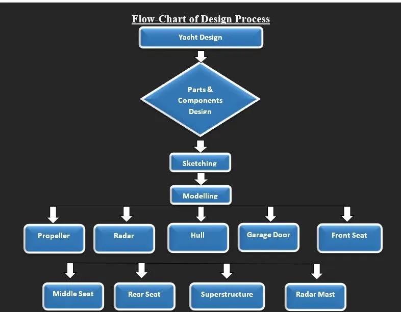
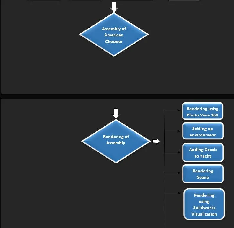
Description-:
Features Used in Drawing
- Boss Extrude-: Boss Extrude feature will project a 2D sketch into 3D model with reference to a plane or face.
- Fillet -: Fillet feature is used to make sharp edges, corners, faces, selected edges round.
- Loft-: Loft feature is used to make complex 3D shapes using profiles, sketches, points, faces & surfaces. This feature joins the different profiles using the guide path provided by profiles, points, surfaces & faces.
- Dome-: Dome feature is used to make a curved surface/rounded surface on the face of the sketch.
- Cut Extrude-: Cut Extrude is the feature that is used to cut/remove a solid area from the 3D extruded model with the reference of the sketch, face/plane.
- Split -: This feature is used to cut/ split the parts/ components into single entities.
- Revolve-: The revolve feature is used to make cylindrical, rounded / revolved model around axis. This feature is useful in making complex shapes around a axis.
- Shell-: The shell feature is used to hollow out the 3D model leaving the faces & creating the thin walls by removing the selected area.
- Linear Pattern -: The Curve pattern is used to make a linear pattern of a sketch with defined increment to a reference of round axis. The pattern can be given a certain spacing/increment & angle too.
- Mirror-: Mirror feature is used to copy the sketch/face/body with a reference of plane/axis.
- Combine -: Combine command is used to combine or add the multiple solid body into a single body/ entity.
- Chamfer-: Chamfer is used to cut the sharp edges/face at a defined angle.
- Curve-: Curve feature is used to make a complex shape/ entity that cannot be made using straight line/arcs.
- Projected Curve-: The projected curve feature is used to project a 3D curve using single/ multiple sketched curves on to a face in a solid body.
- Reference Plane-: Reference Plane feature is used to create a plane with reference to points/face/edge on a body. The orientation of the plane can be defined with the angle value and its direction can be chosen. These planes can be used to construct a sketch/entity on a face in a solid body.
- Sweep -: Sweep feature is used to create a solid body by sweeping a close profile/sketch along an open/closed path.
- Surface Sweep-: Swept Surface is the feature that is use to create a swept surface with reference to the curve along a defined path.
- Surface Trim-: Surface trim is used to create a single solid surface by eliminating the unwanted surfaces from two intersecting surface.
- Loft Surface-: Loft surface feature is used to create the complex lofted surface between the two profiles, sketch/entity.
- Knit Surface-: Surface Knit feature is used to merge/form a single 3d solid body/surface by selecting multiple surfaces. This feature merge multiple surfaces into a single surface/3d body.
- Surface Extrude-: Surface extrude helps you to extrude the surface into a direction with reference to the plane/face/edges.
- Sketch Picture-: This feature helps you to insert the sketch picture in to the drawing. The sketch picture can be used as reference while sketching the geometry.
- Ruled Surface-: This Feature help us to create a tilted and curved surface along the two vertex and edges.
- Surface Extend-: This helps us to extend the edges of a surface up to a distance, edge or face.
- Surface Fill-: This feature connects the two surface and fills the empty area with a curved surface guided along the curve and edges.
- Split Line-: This feature helps us to project a sketch, entity or line on to the adjacent surface, face or plane.
- Surface offset-: This feature helps us to offset a surface up to a certain distance or copy the surface for further use.
- Offset Entities-: This feature help us to offset the sketch entity, line, curve or closed contour up to a distance in 2D or 3D sketch.
- Body Delete/Keep-: This feature helps us to remove and keep the selected face/body from the part or component.
- Surface Cut-: This feature helps us to cut a surface/face/solid body adjacent to the selected surface.
Parts used in Assembly
Propeller-: The Part/component is modelled using following features and commands: Revolve, Fillet, Boss Extrude, Cut Extrude, Circular Pattern & Fillet. The part is given a coloured appearance.
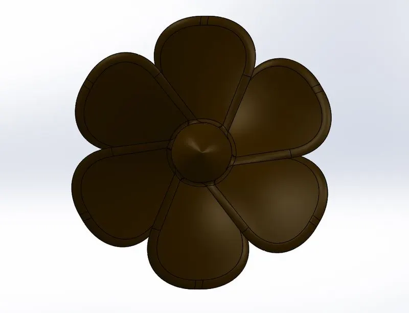
BACK VIEW
Radar-: The part is modelled using the sketch pictures with the help f following commands and features such as Boss extrude, fillet, cut extrude, sketch pattern, mirror, split sine. The part is given a coloured appearance.
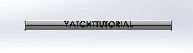
BACK VIEW
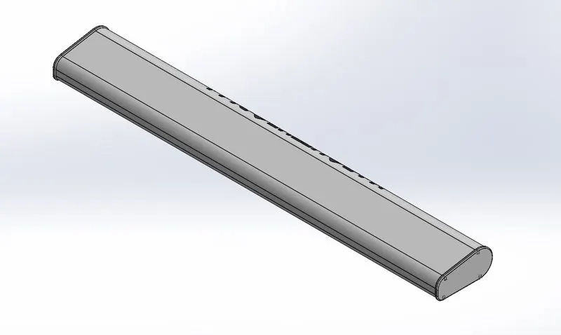
ISOMETRIC VIEW
Hull-: This part is the most complex and major part of this assembly project modelled using following features and commands such as surface loft, surface trim, surface extrude, surface knit, shell, boss extrude, cut extrude, fillet, chamfer, sweep, revolve, body delete/keep, helix spiral, linear pattern, surface offset, surface cut, projected curve, split line, split, dome and mirror, The part is given a coloured appearance.
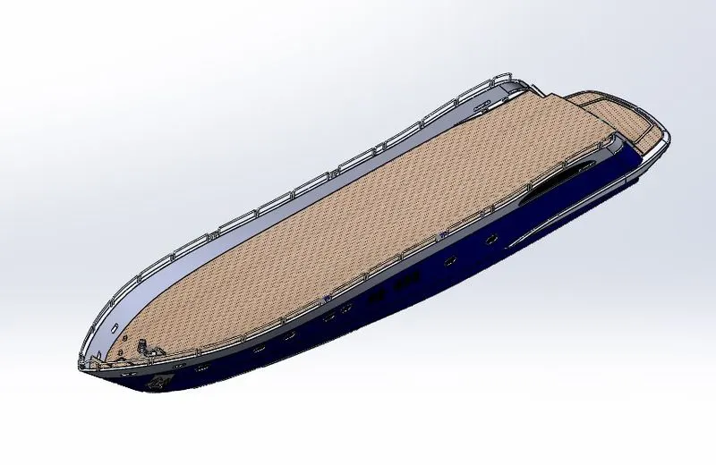
ISOMETRIC VIEW
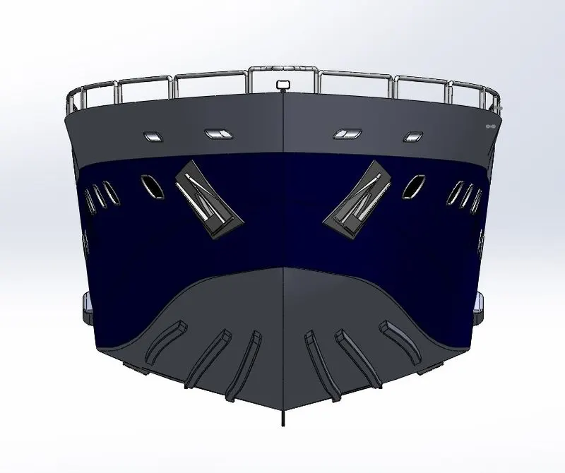
FRONT VIEW
Garage Door-: The part is modelled using the spilt tool and other features such as-: Cut extrude, shell, fillet, mirror, cut extrude & Split line. The part is given a coloured appearance.
BACK VIEW
Front Seat-: The part is modelled using the following commands and features: Surface Seep, Surface Trim, Surface Extrude, Surface Fill, Surface Knit, Cut Extrude, Fillet, Chamfer, Revolve, Mirror, Dome. The part is defined with a coloured appearance.
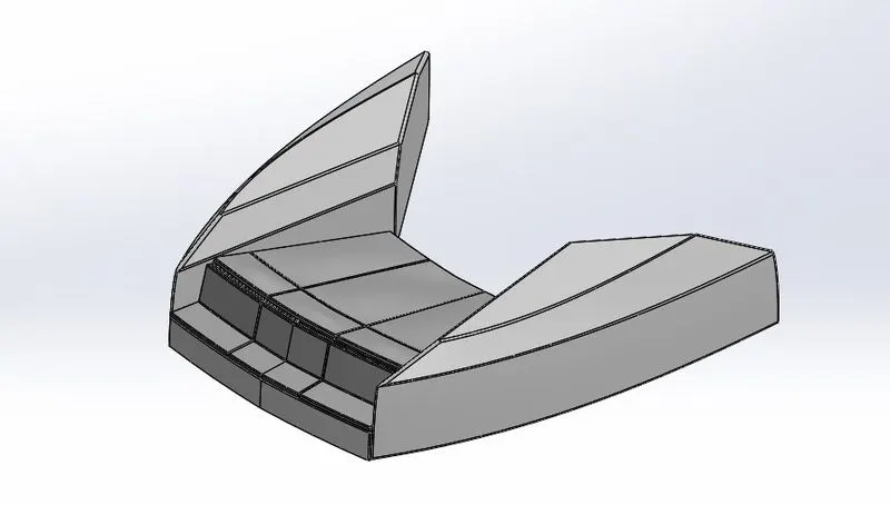
ISOMETRIC VIEW
Middle Seat-: The part is modelled using the following command and features: Boss Extrude, Fillet, Chamfer, Cut Extrude, Mirror & Reference Planes. The part is defined with a coloured appearance.
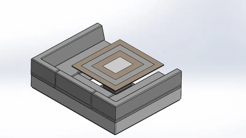
ISOMETRIC VIEW
Rear Seat-: The part is modelled using the following features: Surface Sweep, Surface offset, Surface Trim, Surface Knit, Surface Loft, Surface Extrude, Surface Extend, Boss Extrude, Cut extrude, fillet, reference planes, sweep boss/base, mirror, chamfer. The part is defined using a coloured appearance.
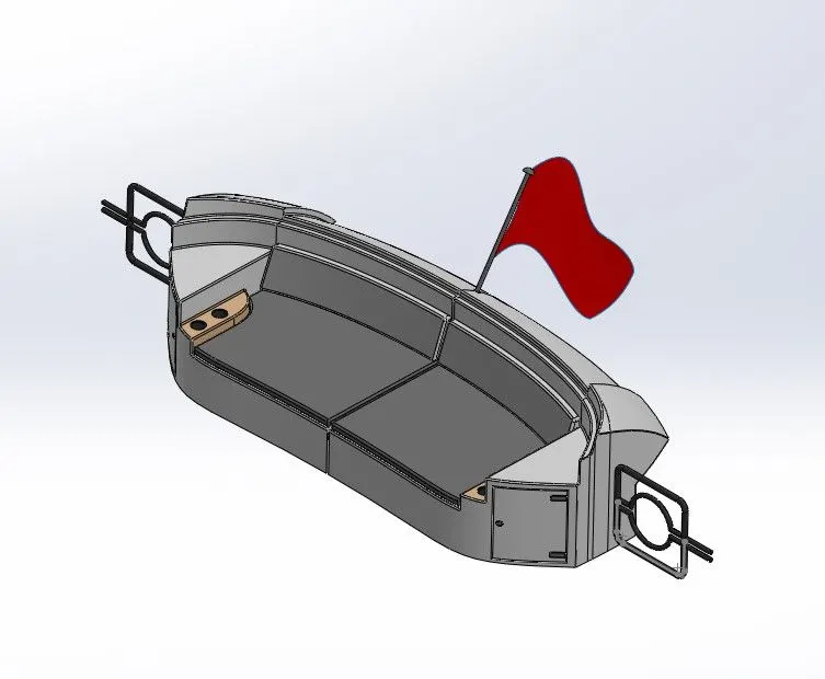
ISOMETRIC VIEW
Superstructure-: The part is modelled and sketched using following features such as surface extrude, body delete/keep, surface knit, surface sweep, surface extend, ruled surface, surface cut, fillet, chamfer, surface loft, surface fill, cut extrude, boss extrude, reference plane, projection curve, split line, delete face, sweep boss/base, chamfer, offset entities. The part is given a coloured appearance.
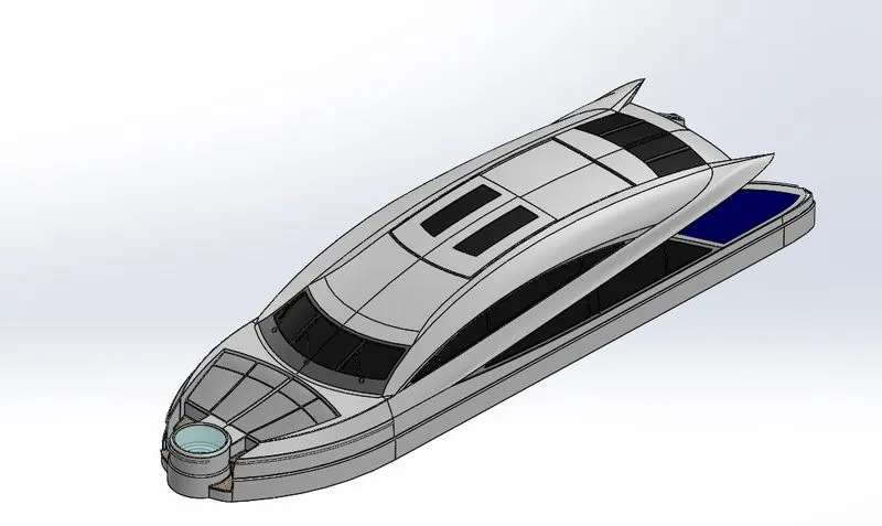
ISOMETRIC VIEW
Radar Mast-: The part is modelled using the following features such as surface trim, boss extrude, fillet, revolve, boss extrude, cut extrude, sweep, mirror, chamfer, dome, shell, mirror. The part is given a coloured appearance.
ISOMETRIC VIEW
American Chopper Assembly
The assembly of Yacht is performed on old traditional technique of Bottom to Top approach. In this type of Assembly process each parts/component are sketched and modelled individually. Then the mates are used to position and align the parts in the assembly.
This project gives insights on Bottom to up approach and how you can put in all the designed parts into assembly and assembled them. In defining mate’s user have to be very specific in defining the relations to the individual parts so that the assembled components function properly.
The types of mates used in assembly of chopper are-:
- Coincident Mate.
- Distance Mate.
- Concentric Mate.
The different views of Assembly are-:
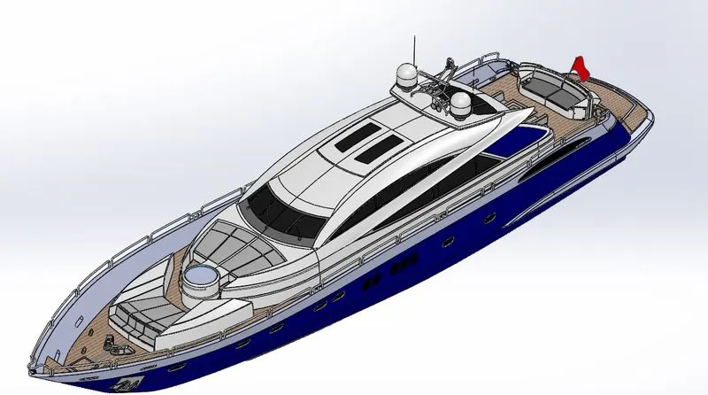
ISOMETRIC VIEW
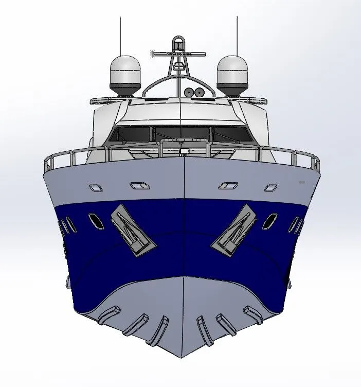
FRONT VIEW
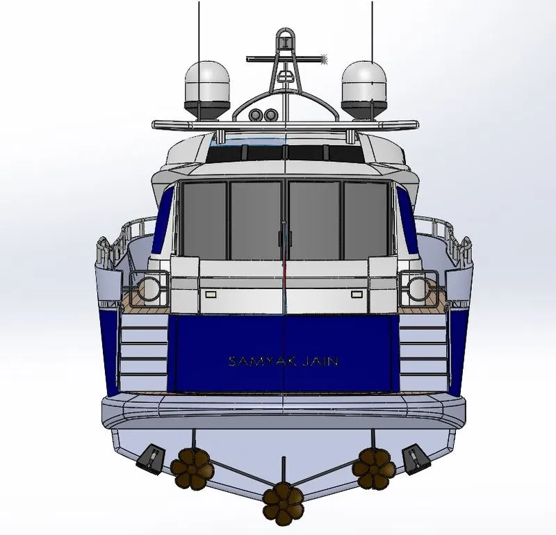
BACK VIEW
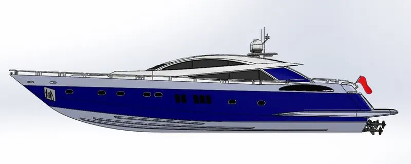
RIGHT VIEW
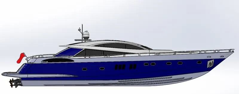
LEFT VIEW
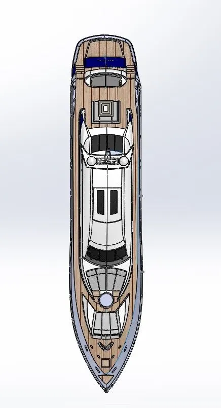
TOP VIEW
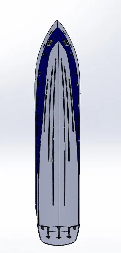
BOTTTOM VIEW
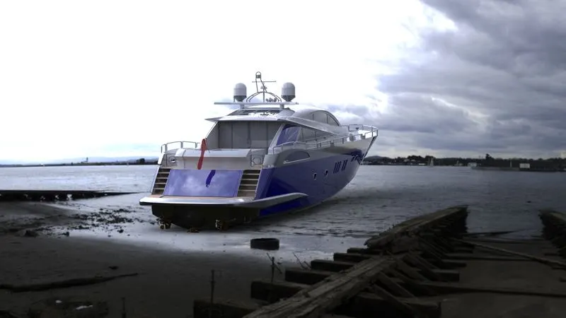
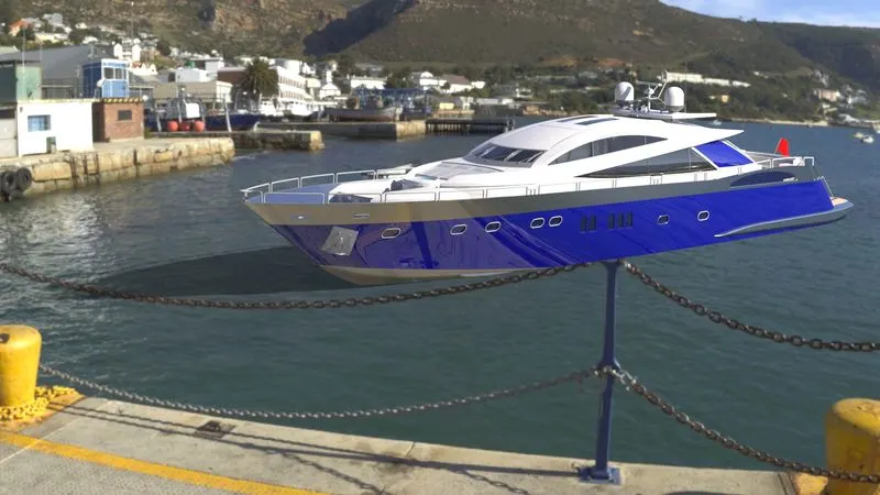
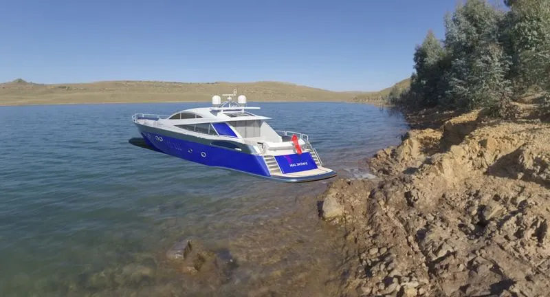
Rendering of Assembly using Photo-View 360 & Solidworks Visualization-:
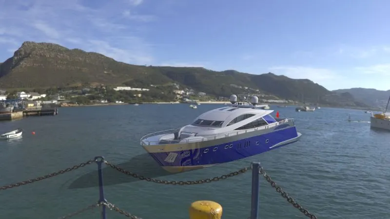
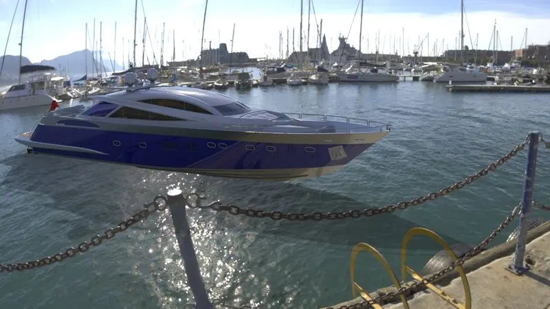
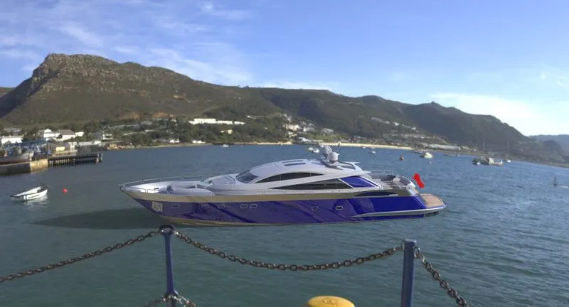
Rendering of Assembly includes rendering of parts, assembled body, setting up of scenes, setting up of environment, setting up of camera, insertion of decals on to the parts, setting up of lights. The rendering process provides realistic view and feel of the 3D object placed in a suitable environment.
The rendering process in this project provides us an understanding on what is the importance of setting up scenes, and how to play with the environment to provide the 3D assembled body a realistic view. The camera setup such as change of focal point, different camera views & perspective view of camera. The Environment setup gives us instance on how to play with brightness, contrast and other settings to enhance the appearance of the object. The rendering process in visualization taught us how we can play with the appearance of each component, apply material to each component and play with them to get a perfect realistic experience of the assembled body.
Some of the rendered assembly views are attached below-:

Conclusion-: This Project provides us a brief learning on how to sketch & model your ideas into 3D sketch using the features & tools in Solidworks. The assembly tasks provide us glimpse on Bottom to Top approach the traditional method used for assembly of parts & components.
The Rendering tasks provides us instances on how to play with scenes, lights, camera & environment to provide a realistic experience of your object. Overall learning from this project can be concluded that it provides you the exposure for the industrial projects as well as the deep understanding & strong hold on the basic concepts of Solidworks.
The following Yacht project gives us an immense exposure on Solidworks basics & advanced features & tools.