Hood design-Week 2
HOOD ASSEMBLY
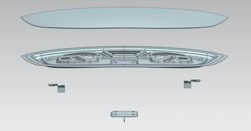
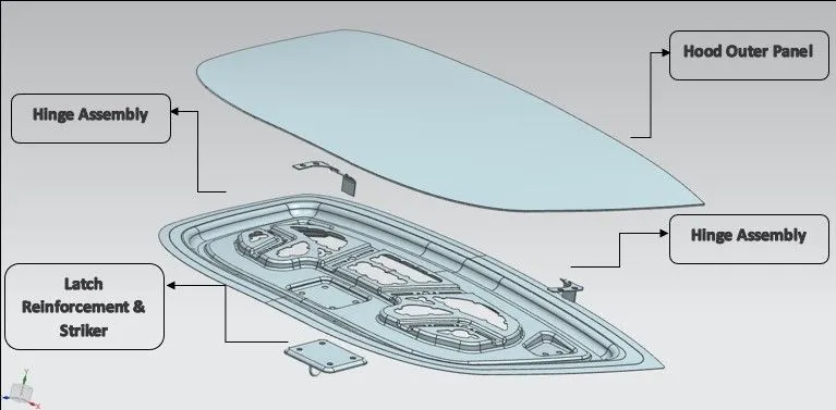
1. Objective-: The objective for this project is to understand the concept of sheet metal designing in UG NX as per industrial standards. The project gives us brief insights on the manufacturing & industrial regulations used in designing & assembling the sheet metal components. We learnt the top to down assembly approach in this project. Some of the major components of hood assembly is -: a. Hood Outer Panel.
b. Hood Inner Panel.
c. Striker.
d. Hinge Assembly.
We have been provided with a master sketch & Class A surface in reference to which we need to design and assemble our project. Some of the major challenges faced during this project are-:
a. Designing of Inner panel (Includes Embossing, law extension, defining of mastic points).
b. Defining of reinforcements for Striker & Hinge assembly.
c. Hemming of Outer panel.
d.Defining hemming reliefs.
Some of the safety standards that need to be kept in mind while designing of hood are-:
a. Opening angle of hood as per the nation car is designed for.
b. Positioning and designing of hinge assembly as per the hood design and weight.
c. Designing of hood structure such as to reduce the head impact as low as possible while keeping the strength & design in mind.
d.Hood structure is to be designed such as it absorbs maximum forces during accidents and collision.
2. Introduction-:
The Hood Assembly project provides us brief insights and knowledge on Automotive sheet metal designing using NX Cad/Catia V5 while considering pedestrians safety and vehicle safety. The project is made using Top to Down Assembly approach. The design of the hood is made while considering manufacturing practices and industrial standards.
3. Designing & Assembly of Car Hood-:
The front hood is one of the major panel and component of car. As it is important not only from safety point of view but it provides aesthetic appearance and endurance to the car structure. While designing the car hood some aspects are needed to be considered such as appearance, safety of passengers and pedestrians, aerodynamic efficiency etc.
The Car hood design and assembly comprises of following components-:
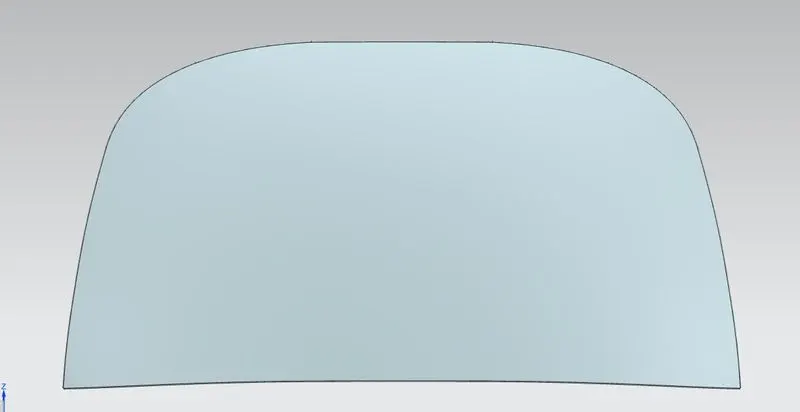
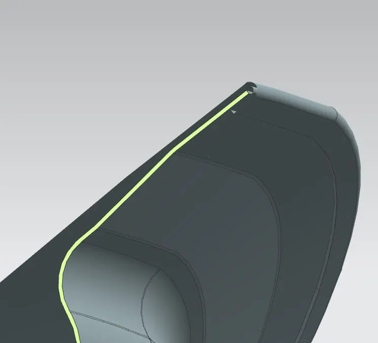
- Outer Panel-: Outer panel is the outermost surface of the car hood; it provides aesthetic looks and appearances to car hood. The Outer panel is the class-A surface designed using software’s such as Catia & Autodesk Alias. The outer panel is the component which is taken as reference to develop the inner panel. The outer panel is joined with inner panel using hemming process. The hemming reliefs are also provided to the outer panel. The outer panel is thin and weak not able to hold/transit the impact forces. Its thickness is 0.75mm.
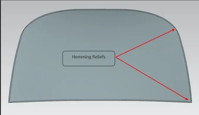
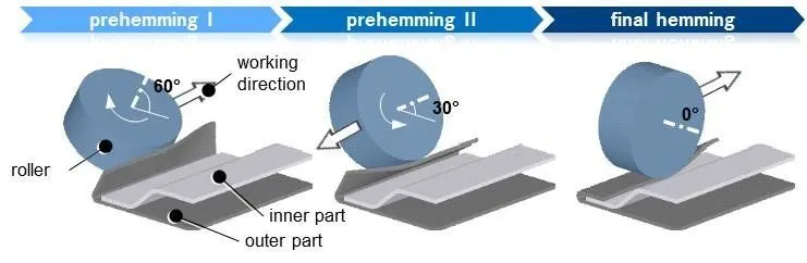
i. Hemming-: Hemming is the process of joining sheet metals by bending them to 180 degrees. The Automotive body panels such as doors, back panels, hood panels are joined using hemming process. This process is also known as sheet metal forming process. The hemming process can be classified in two types -:
a. Conventional Hemming –

b. Roller Hemming-:
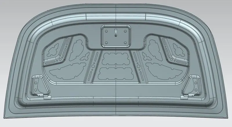
2. Inner Panel-: The Inner Panel is the engineered part/component from Outer Panel. The inner panel consists of embossed faces and ribs to provide the strong structure and strength to the hood. The inner panel is designed while considering some factors such as the manufacturing aspects, safety aspects, support rod, hinge assembly & latch reinforcements. Its thickness is 0.75 mm.
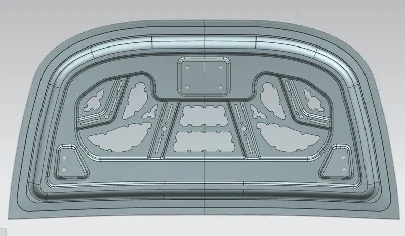
The Inner panel design and structure provides strength and endurance to the hood assembly. The inner panel is designed such as that the collision forces is minimized, absorbed or transmitted to reduce the impact to minimum. The various aspects kept in consideration while designing inner panel are-:
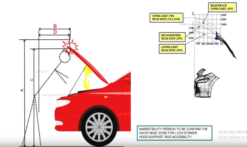
a. Head Zone clearance for striker position – The striker lock position varies for the region or the nation the car is designed for. The same car will have different clearance for head zones. The hood opening angle also depends on the same. The marketing person will provide data for the head clearance.
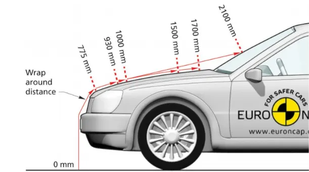
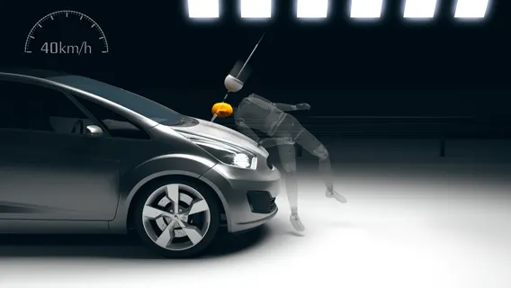
b. Wrap Around Distance-: During the most accidents the pedestrians wrap around the car front shape and suffer head impacts on bonnet/hood or windshield. In most euro cap standards frontal collision with pedestrians are tested for head impact analysis.
According to data, nearly 10% of pedestrians fatal each year by accidents in India. This study reveals every second pedestrian accident occurs while walking and crossing the road.
Considering the above facts car hood inner panel structure is designed such as to reduce the impacts during head collisions.
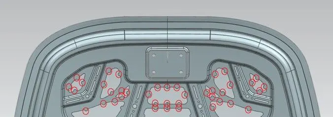
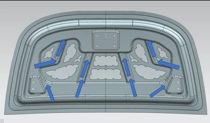
c. Mastic Points-: Mastic Points are the points that are provided for applying mastic sealants to join the inner panel and outer panel. Mastic sealant is a rubber type sealant which when heated gets hardened and joins the adjacent surfaces. The mastic points have an influence area of 80mm. The mastic points are highlighted in the below image for your reference.
The Mastic points provide good NVH value. Mastic points are provided such that they covers major of the hood panel except the reinforcements for hinge and latch. The Mastic points provide a huge reduction in NVH Value.
I had highlighted the points in the below image where the mastic points have been provided.
d. Flanges-: Flanges are made using the master section provided for hood inner pannel.
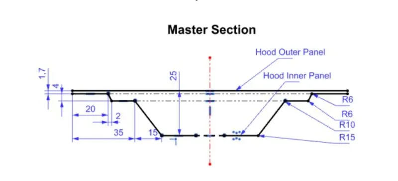
e.Embosses-: Embosses are the raised faces or edges on a sheet metal surface to provide extra strength and endurance to the part. The embosses also helps to ddissipate the front collision forces to side pillars and edges of the car and helps to minimize the impact towards the passengers. The embosses are designed in such a way to provide maximum strength and reduce the impact during collision.
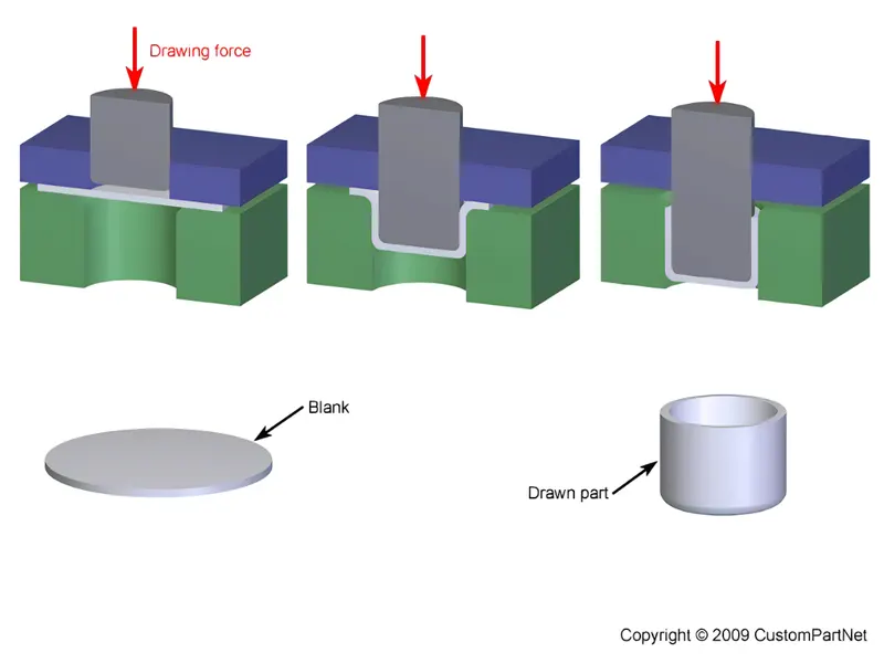
f. Deep Drawing-: Deep drawing is a sheet metal forming process. In deep drawing process complex shapes and designs are formed from sheets using die and punch. The sheet is called blank on which the pressure is applied by the punch and blank is formed into a shape. The Inner hood pannel is designed considering the deep drawing process a positive draft angle is provided too each embossed and extended face.
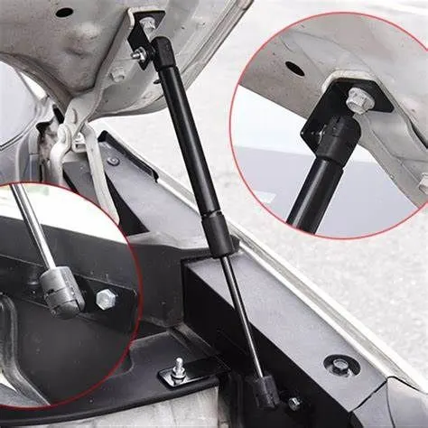
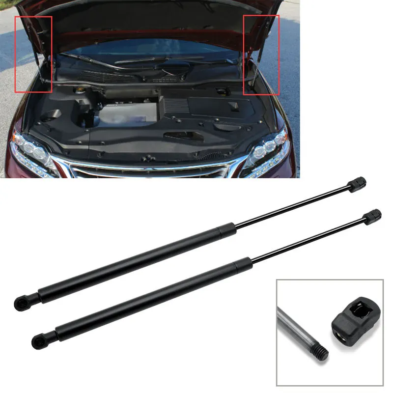
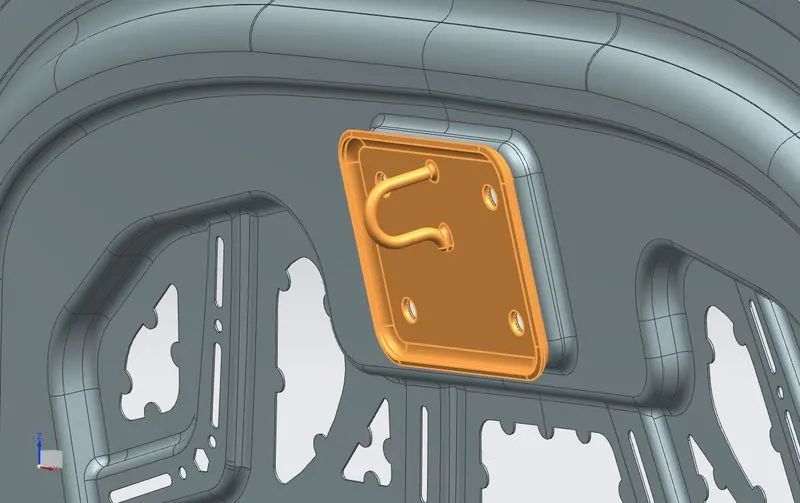
g. Support Rod & Gas Stay-: Support rod and Gas stay are the support mechanism when the hood of the car is in lifted position. When we unlock the latch of the striker and lift the hood the support rod & gas stay comes into play for support the hood at the defined opening angle. The support rod can be mounted on hood inner pannel as well as the engine compartment. But gas stay is always mounted on the engine compartment. Gas stay is used for heavier hoods while support rod is used most commonly in cars.
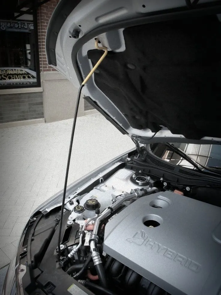
Support Rod
Gas Stay
3. Hinge Assembly -: The hinge assembly is a mechanical joint that revolves only on its axis. The hinge assembly allows the hood to open at limited angle and thus working as a movable joint for hood. The hinge assembly gets clamped on the engine compartment over the fender region and on the hood inner panel. Due to its mounting over the engine compartment it is exposed directly to the vibrations and thus to provide enough strength and endurance the emboss is provided on the hood inner panel. This works as an reinforcement and thus not only provide strength but eliminates vibrations too. The hingle assembly reinforcement thickness is 1.5 mm thus providing rigidity to the hinge assembly.
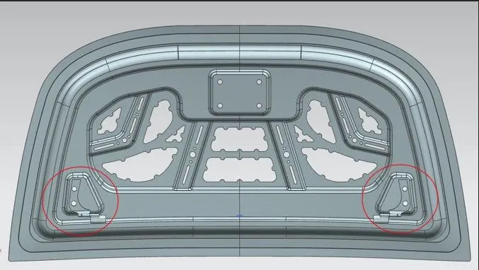
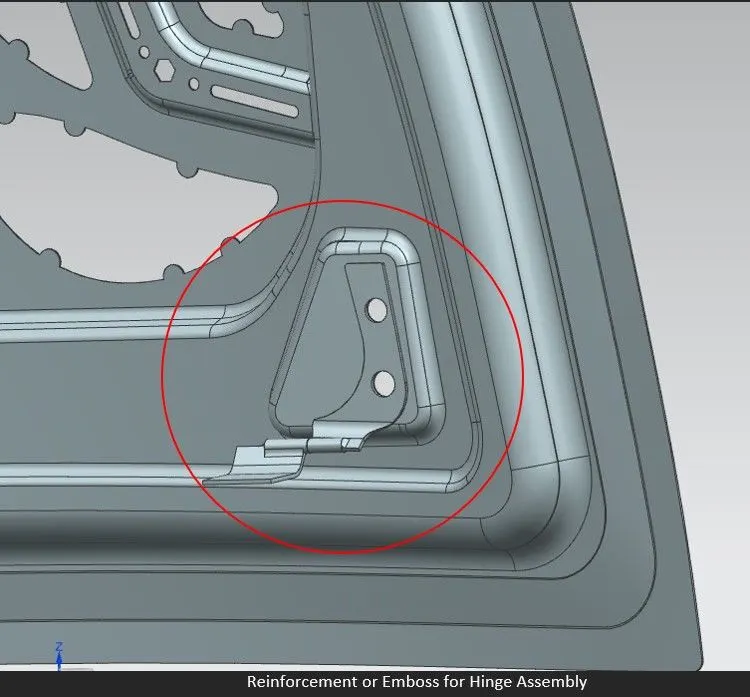
4.Latch Trajectory & Striker -: The latch Trajectory is important for striker positioning. If striker positioned at correct positioning the opening & closing angle for the hood will be appropriate. The latch trajectory is determined by the hinge assembly axis with the help of circle from hinge axis midpoint. The striker assembly should be perpendicular to the circle and in orientation with it. The striker is the part/component that gets clamped in the latch mounted on the engine. It helps to lock the hood when in closed position The striker positioning is most important for that we need the latch trajectory.
Conclusion-: The hood project is designed using the master sketch & class A surface and its assembly is done using the Top to bottom approach.
The project gave us the brief insights on the design standards & safety standards used in industries. The design structure of the hood provides us insights on clearance & tolerances to be kept in consideration for manufacturing. The project taught us how to work on surfaces in sheet metal designing using NX Cad. The overall conclusion of this project is to provide industrial exposure to students how designs are made in real world.
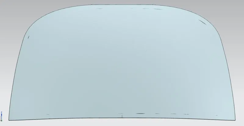
A. Front_View_Hood_Assembly-:
B. Back_View_Hood_Assembly-:
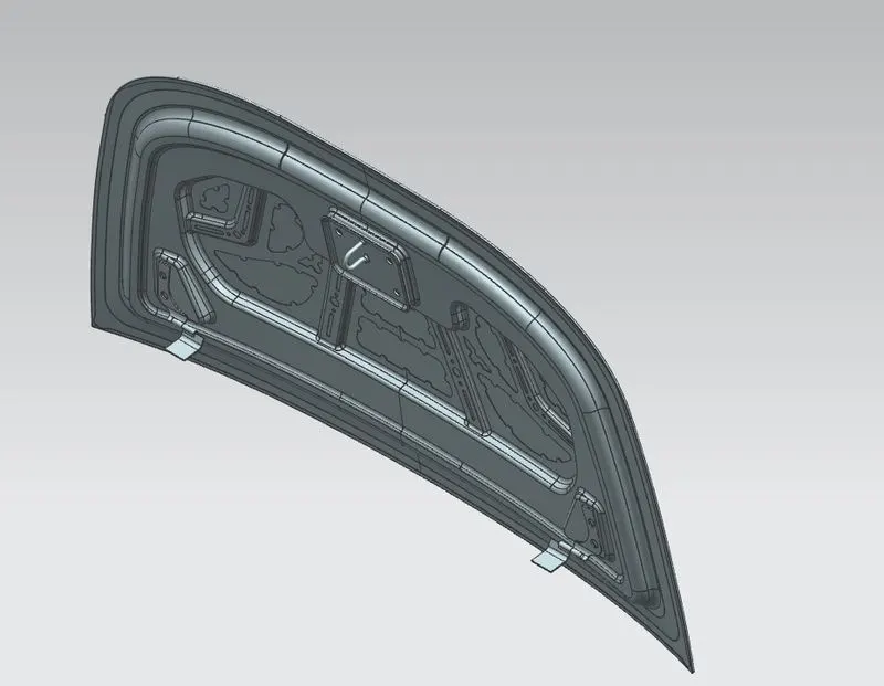
C. Isometric_View_Hood_Assembly-:
D. Top_View_Hood_Assembly-:
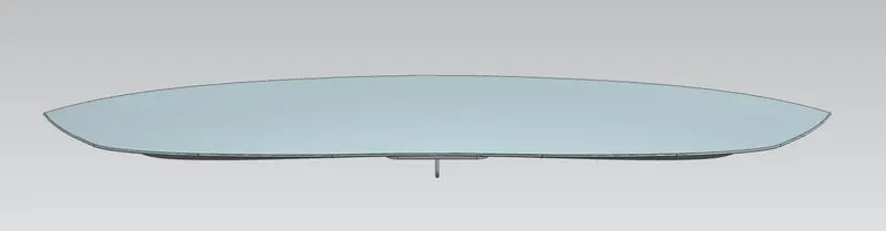
E. Bottom_View_Hood_Assembly-:
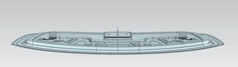
F. Exploded_View_Hood_Assembly-: