Wiring harness routing & packaging Rules Week 3 Challenge
WIRING HARNESS ROUTING &PACKAGING WEEK 3 CHALLENGE
AIM-To download P clamp cad data & define it as Electrical support using Electrical Part design Workbench. To download back shell cad data & define it as Electrical back shell using Electrical Part design Workbench. To create corrugated tubes & add them in catalogue under “COT” family.
INTRODUCTION
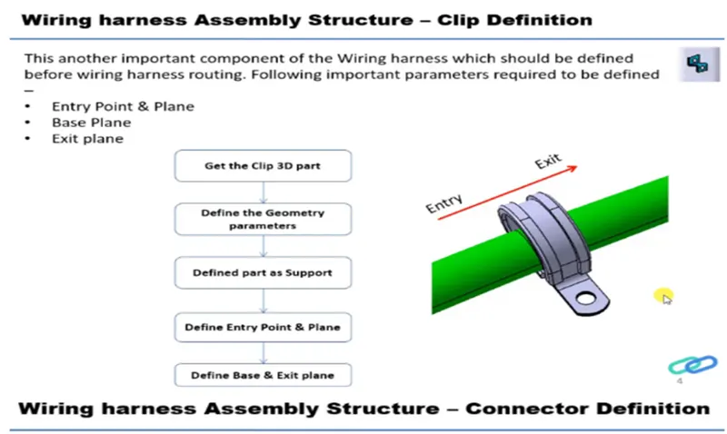
- P clamp: - P-clamps lock cables and hoses in place and help ensure that machinery, vehicles and equipment keep running. They bracket wires, cables or hoses together mechanically and are fastened securely to an anchor point – usually with a screw or a bolt.
- Back shell: - A back shell is a mechanical device threaded into the rear of an electrical connector used to provide some additional support as well as improve the aesthetics of the wiring harness.
- Corrugated tubes: - Corrugated conduits and protective hoses with various properties, from heat resistance through abrasion protection and impact strength to noise reduction, protect valuable cables against all unfavorable external influences.
DESIGN METHODOLOGY OF P CLAMP-
- First open the 3D CAD data in Catia and then convert the file format (ex: igs, Stp) to. CATPart.Start the Part Design Workbench in Catia.
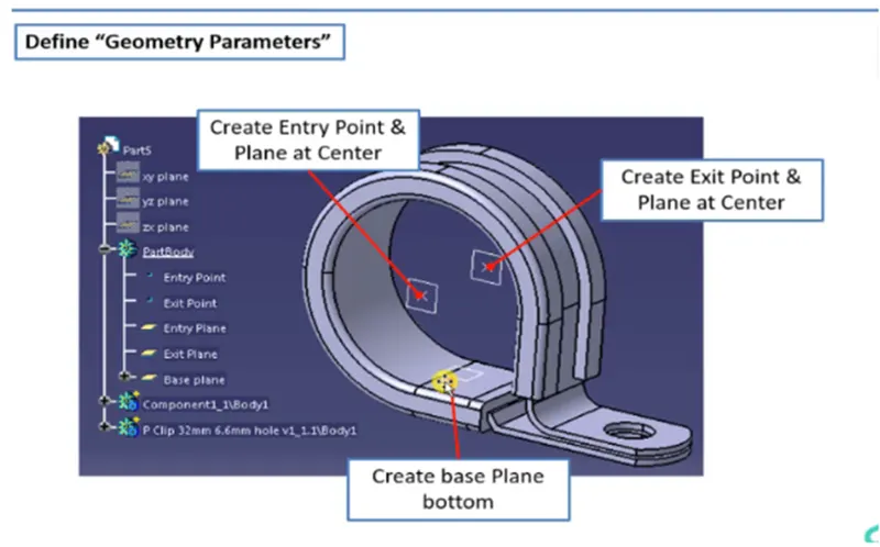
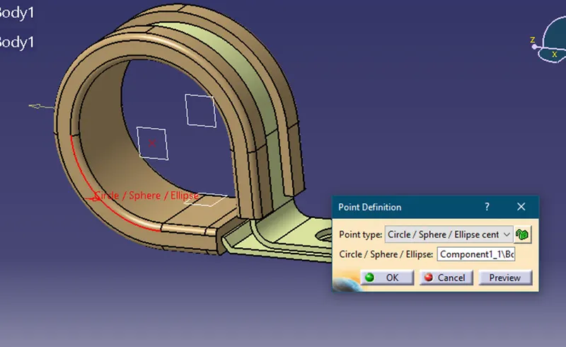
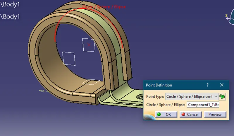
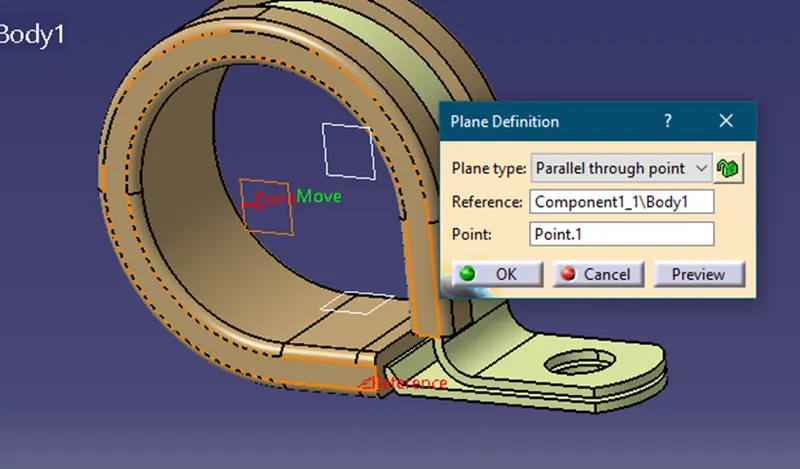
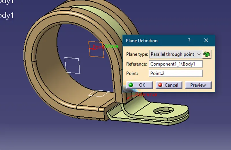
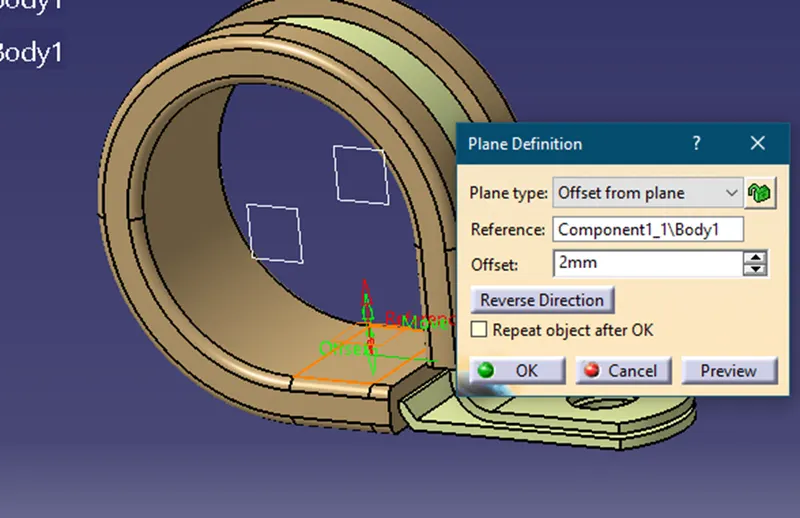
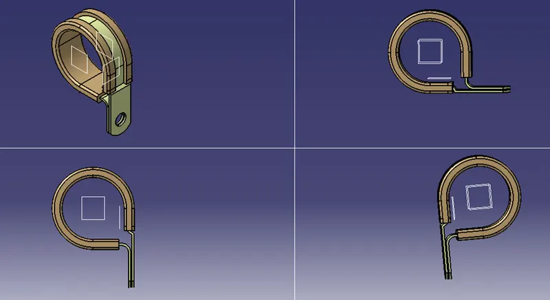
- Define the CAD model geometrically by adding one entry point and one exit point. Also, we have to create two planes with these two points as reference as well as one another plane as a reference for the base of clamp.
- Then start the Electrical Part Design Workbench in Catia. Click on Define Support Part option from the toolbars and the select the clamp body, then we have to select any one of the two points as our entry point along with the reference plane and then we have to select the second plane and the base clamp. Click on ok.
- After that we have to once again select the Define Support Part option and then we have to select the second point this time as our exit point, the plane containing this point then then the base plane. Click ok. this will fully define our clamp as an electrical support.
- Save the file.
DEFINING BACK SHELL AS ELECTRICAL BACK SHELL
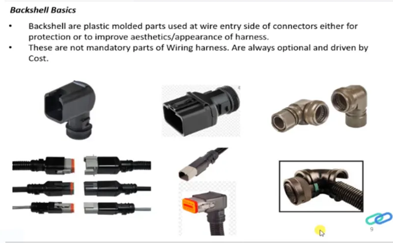
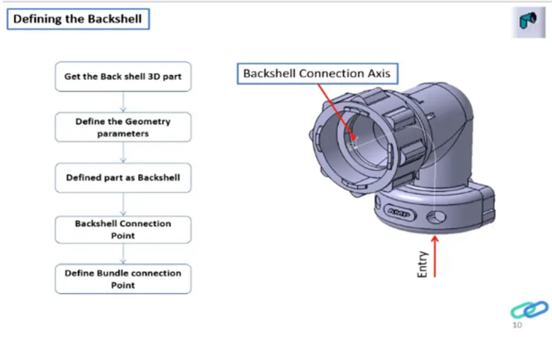
- First open the 3D CAD data in Catia and then convert the file format (ex: igs, Stp) to. CAT Part.
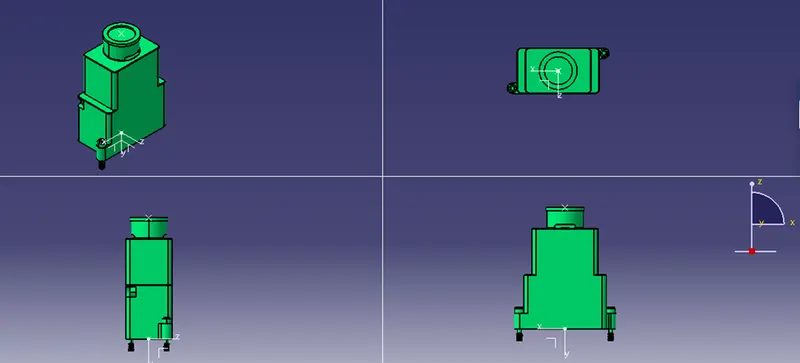
- Then define the back shell geometrically in the Catia Part Design Workbench. To do that we have to first assign a mid-point to the bundle connection side face of the back shell and then we also have to assign a mid-point to connector connection side of the back shell, along with that we also have to assign an axis system on the mid-point of the connector connection side face. This will allow us to fully define our back shell geometrically.
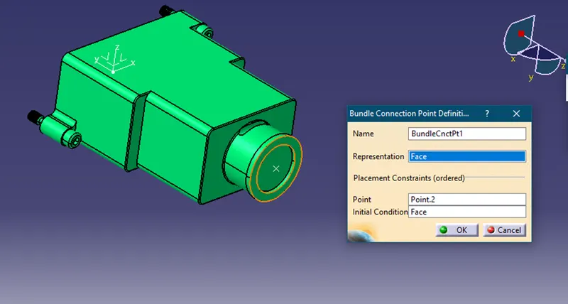
- After that start the Electrical Part Design Workbench in Catia to define the back shell electrically. First, we select the define back shell option from the toolbars and then we select the back shell body and click ok. Then we select the define bundle connection point option from the toolbars and then we select the back shell body, bundle contact face for representation, mid-point for point, and again bundle contact face for initial condition and then click on ok.
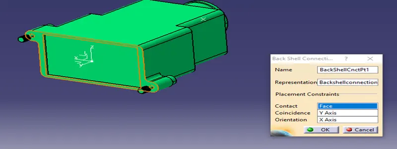
- we select the define back shell connection point option from the toolbars and then we select the back shell body, mid-point for representation, contact face for contact, Y-axis for coincidence and X- axis for orientation and then click on ok. This will fully define our back shell electrically.
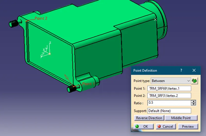
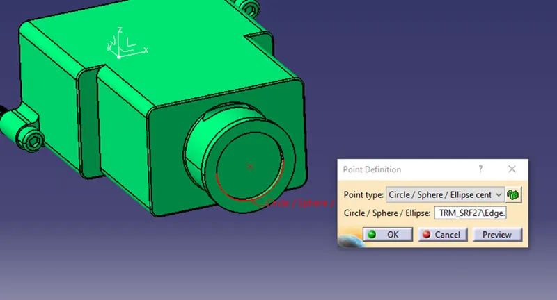
CORRUGATED TUBES
- Create a new catalogue document. Give "Slit COT" as name and conduit as type. Save the file.
- Start the Electrical Part Design Workbench in Catia. Select the Define Protection Part option from the toolbars and then select the part name from the feature tree.
- A Define Protection Part pop-up window will appear where we have to assign the required values of inner diameter, thickness, and bent radius. Click ok.
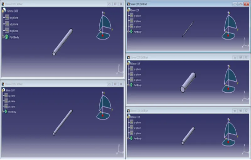
- Our desired corrugated tube will be created.
- Then we have to add out model to the "Slit COT" catalogue that we created. Save the Files. We have to repeat the same process for creating all the corrugated tubes of required diameter.
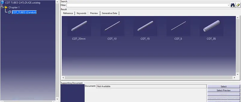
Catalogue Document