Wiring harness routing & packaging Rules Week 3 Challenge
WIRING HARNESS ROUTING AND PACKAGING
Aim:
To download and define the given cad data for P-clamp, Back shell and define them using proper electrical commands, and to create the corrugated tubes for the given size and to create a catalogue under slit cot family.
Procedure:
For defining the P-clamp we need to follow the below steps.
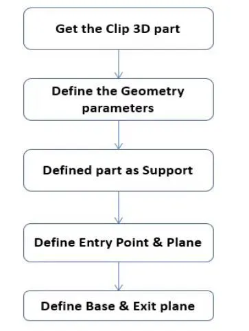
By following the above steps have downloaded the P-clamp 3d part, then we have to define the part in the CATIA V5 electrical part design work bench. It is shown in the below steps
- Create the required geometrical inputs needed for defining the supports, we need to create the entry and exit points and corresponding planes and also a base plane.
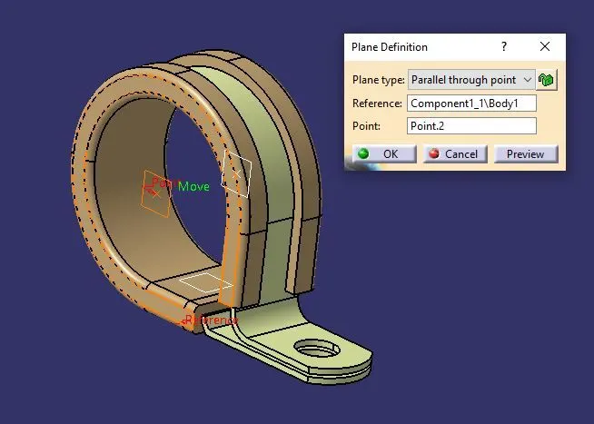
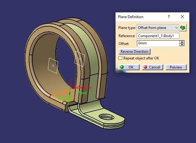
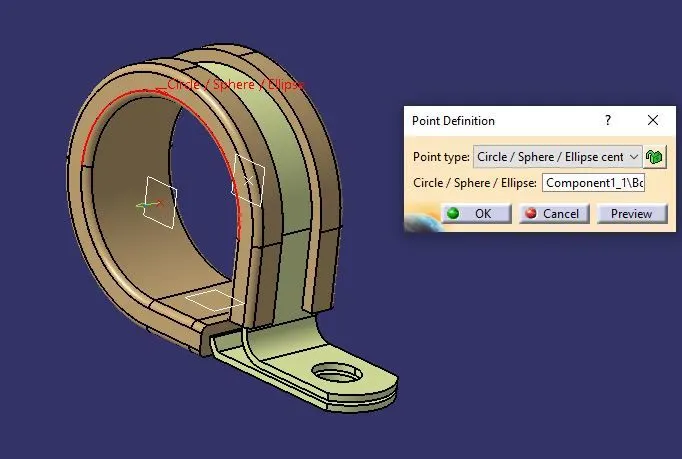
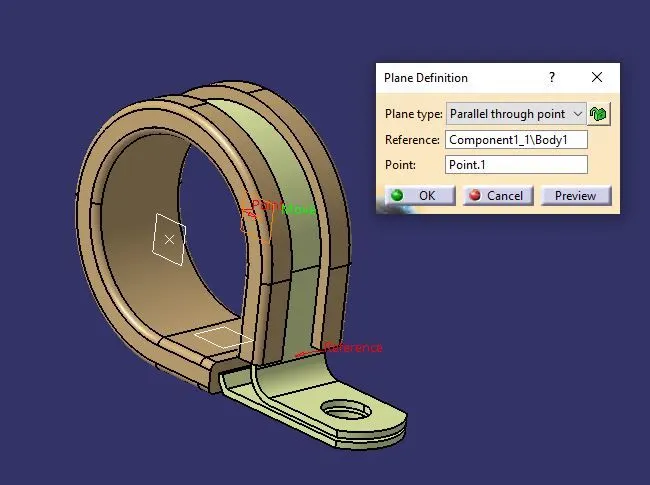
- Define the part as support using the define support part command and select the P-clamp.
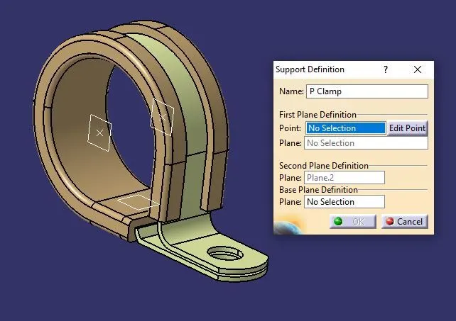
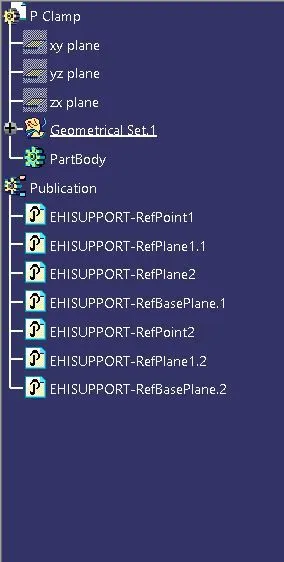
- Here while defining the part as a support we need to define the part twice and we need to swap the selections for the second time selection to create two entry points.
For defining the back-shell we need to follow the below steps.
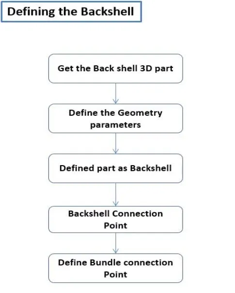
- Download the back-shell cad data from the website by entering the suitable part number.
- Create the required geometrical parameters for back-shell, for a back-shell we need to create point and axis system as shown below.
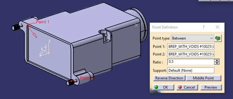
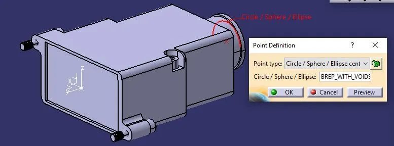
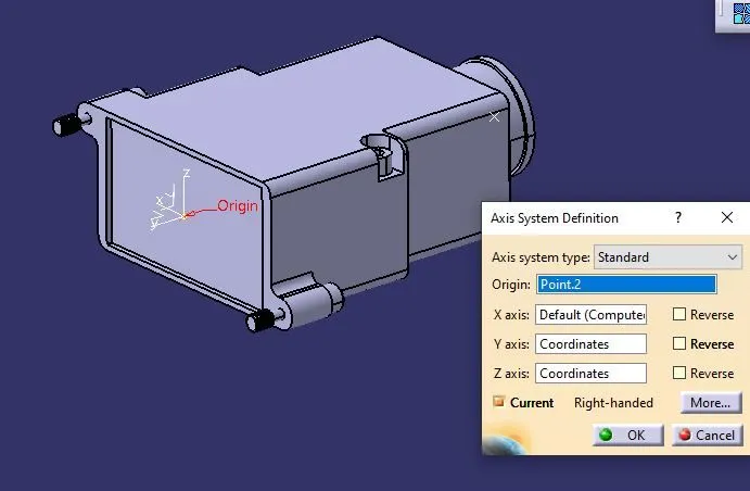
- Then define the part as back-shell using the back shell definition command.
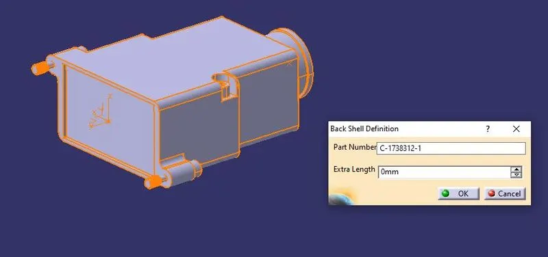
- Define the back shell connection point, this back shell connection point is considered for connecting with the connector.
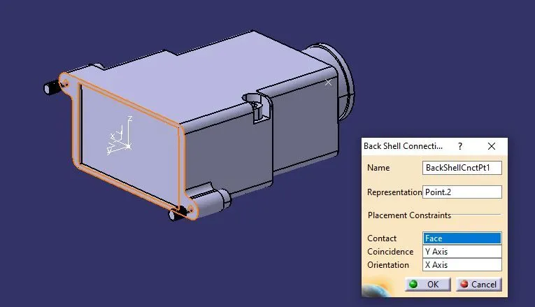
- By using the back shell connection, command we can define the back shell connection point which is going to be connected with the connector, and we need to choose the proper face, coincidence axis also for perfect mating of the back shell with the connector.
- Define the bundle connection point using the bundle connection definition command here also we have to choose the appropriate face coincidence axis and points for perfect mating with the component.
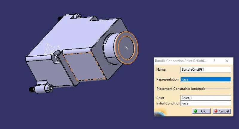
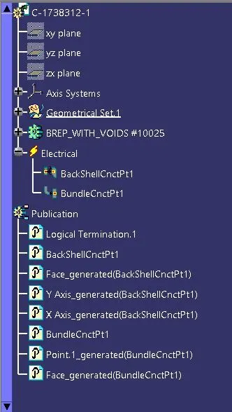
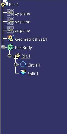
- Then to create the corrugated tubes we need to open the new part file then switch to the electrical part design work bench.
- Then select the define protection part command and select the part body of the window.
- Then we have to enter the values of the inner and external diameter of the tube and we have to select the appropriate bend radius also, normally the bend radius for the cot tube should be 1.5 times the external diameter of the cot tube.
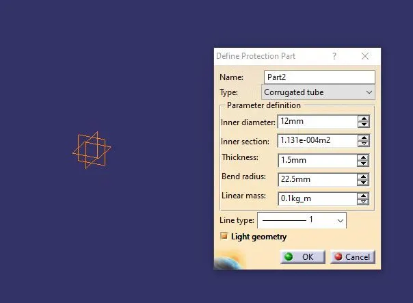
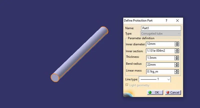
- Also the larger the bend radius the tube will be less flexible, if the bend radius is less the tube will be more flexible.
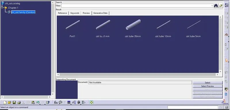
- By this similar way need to create the other protection cot tubes also, for various values. Then we need to create the catalog part file that should be saved on the same location of where the cot tube files are also saved.
- Then use the device storage option to store the created part file onto the same location, by browsing and navigating the location and adding it on the cot tube family.
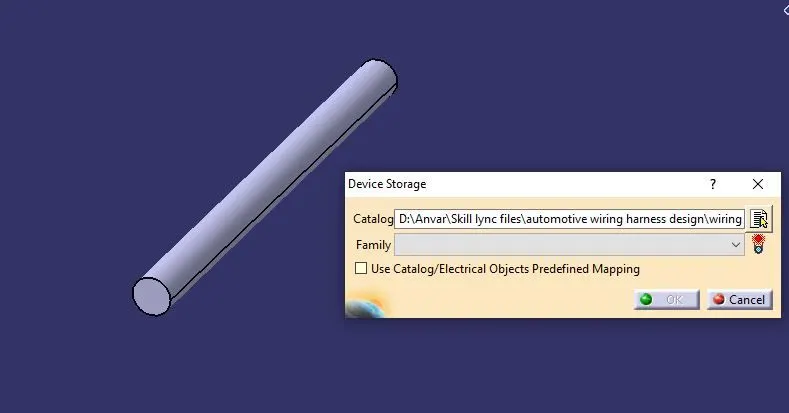
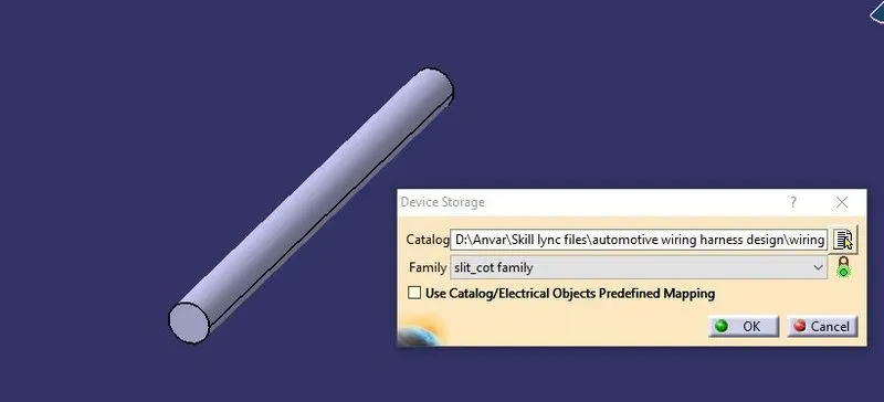
- Then we can navigate the catalog file and we can open it on the CATIA to ensure we have created all the cot tubes and we can ensure that all are available or not.
CONCLUSION
Thus the back-shell, clamp and cot tubes are downloaded and their electrical properties are defined.