Radar Mast & Final Assembly of Yacht
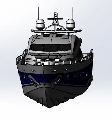
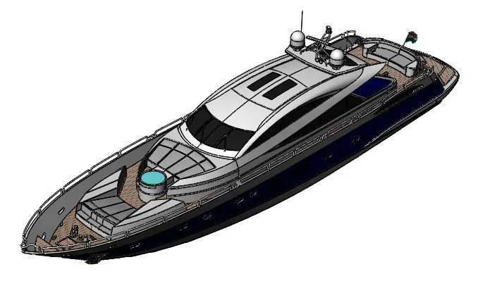
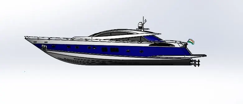
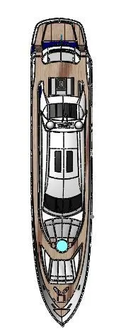
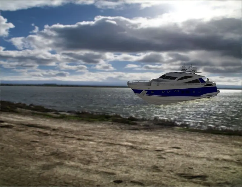
MODELLING AND RENDERING OF SUNSEEKER PREDATOR YACHT
OBJECTIVE
The main objective is to create the model of the sunseeker predator yacht, assemble and render.
INTRODUCTION TO SUNSEEKER YACHT MODELLING
In this yacht modelling I have created each and every part of that yacht using various commands and various operation in solidworks. Modelling this yacht includes various commands and the various ways of execution for the same command. In assembly modelling also used various mates not only coincidence, concentric, distance mates also. In rendering the photo realistic approach is given using photo view 360.
DETAILED DESIGN APPROACH OF YACHT MODELLING
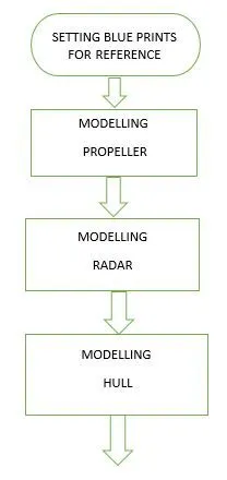
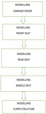
The detailed design approach for modelling the yacht is given below as a flow chart

VARIOUS PARTS OF SUNSEEKER PREDATOR YACHT
1.Propeller
2.Radar
3.Hull
4.Garage door
5.Front seat
6.Middle seat
7.Rear seat
8.Super structure
9.Radar mast
Features/commands used
1.Sketch
Sketch is a command which is used to create the 2d outline of the part to be modelled according to the view. According to the view various sketch planes are used to create a sketch of the part by using various commands like line, circle, rectangle, arc etc. Sketching is the most important thing to create the 3d part, each and every sketch need to be constrained, under defined and over defined sketches may create errors.
2.Line
Line is a command which is used to create a line on a sketch. Line is a very basic tool used to create a 2d drawing. Various types of lines are used in solidworks they are mid-point line, tangent line, construction line etc.
3.Circle
Circle command is used to create a circle in solidworks. Here perimeter circle is another type of circle.
4.Rectangle
Rectangle command is used to make the different types of rectangle in solidworks, various types of rectangles are used, according to the designer’s ability to draw a component easily. some of the rectangle commands are three-point rectangle, corner rectangle, centre rectangle, etc.
5.Offset Entities
Offset command is used when we are in sketching environment, and this is used to copy the existing edge of an object or line or curve of a sketch to specified distance and direction.
6.Ellipse
Ellipse command is used to create ellipse with major and minor axis. This command is used here to create a kickstand in this chopper modelling series.
7.Convert Entities
Convert entities is used to convert the edge of a part to a sketch plane according to the view. Here the edge may be a cure or a line or it can be any geometry.
8.Spline
Spline command is used to create a line which has curves on it with control points and spline handles. We can add more control points to control a spline. This spline command is used to get a nice curvature.
9.Boss Extrude
Boss Extrude is a command which converts the 2d sketch into a 3d object or part. Extrude is a metal adding feature. This feature has various options on it, like mid plane extrude, draft, etc. These various options are used according to the necessity.
10.Cut Extrude
Cut Extrude is a command which is used to remove material from the 3d object. This extrude cut is also have various options like the extrude command.
11.Revolve
Revolve is also a metal adding command which add material according to one rotational axis or centre axis. This revolve feature is also having various options like selected contours, angle of rotation etc.
12.Revolve cut
Revolve cut is the feature which removes the material from a 3d object according to the sketch drawn and centre axis. This revolve cut is also has selected contour and other options.
13.Fillet
Fillet is a feature used to avoid the sharp edges of the part by making them rounded corners. fillet is given to avoid the damage made by the sharp edges of a component to other components or to persons handling the object.
14.Chamfer
Chamfer is another edge treatment process this will also produce safe corners when compared to sharp edges. Various types of chamfers are available here in solidworks. Chamfer can be provided by using distance by distance, distance by angle etc.
15.Projected Curve
Projected curve is a curve created by projecting two different 2d curves drawn on two different planes, the intersecting area of these two curves are created as a new curve.
16.Sweep
Sweep option is used to create a 3d part using a sketch and a trajectory. The 2d sketch and the trajectory (sweep path) drawn should be in different planes.
17.Loft
Loft option is used to create a sweep between two different sketches with a fine transition. We can create loft using guide curve, or centre curve options.
18.Dome
Dome is a feature used to create a rounded vault like structure on the selected flat circular face. It may be elliptical or non-elliptical dome and continuous dome on the filleted edges also.
19.Circular Pattern
Circular pattern is a feature used to create copy of the modelled part with controlled instances and angles according to the centre line. We can select geometric pattern in this circular pattern.
20.Linear pattern
Linear pattern is a feature used to create number of copy of the modelled part with controlled instances and linear distances. We can select number of rows and other options in this linear pattern.
21.Split
Split is a feature used to split a part in to different bodies with different possibilities, consume cut bodies can be used for various results. Split is a powerful tool which can use a face, surface or a single open sketch as a splitting tool.
22.Extrude surface
Extrude surface is a feature which helps to extrude the line drawn into a surface. surface is having no properties of mass defined and no thickness. And this extrude surface has various options on it which allows us to extrude the surface and also to make a capped end, and knit surface options in a single command.
23.Boundary surface
Boundary surface feature is used to make a surface with the selected lines or edges of a surface as a boundary region.
24.Knit surface
Knit surface feature is used to join all the surfaces drawn into a single surface it also joins and eliminates the gaps between the surfaces by joining the surfaces. This feature has various options on it such as try to make solid, this option enables us to make a solid out of surface.
25.Shell
Shell, as its name suggests shell command is used for shelling purpose. We can create internal shell for a closed body with the assigned thickness or we can also create a open face by selecting the faces during the shell command.
26.Lofted surface
This feature is used to create a surface by creating section curves and guide curves. These section and guide curves are used to make the lofted surface.
27.Combine
Combine is a command which is used to perform different operations between two solid bodies. We can add, subtract or intersect them to create a new component.
28.Dynamic Mirror
In this dynamic mirror feature we have to select a construction line which acts as a reference line for mirroring the drawn sketch. This command will actively mirror the sketches drawn.
29.Move copy
This command is used to move the created component in the 3d space. The proper coordinates for the movement of the part from one coordinate to another should be given correctly.
30.Appearance
The proper appearance helps to identify the component and it will make it more attractive. There are different types of appearance like chrome plated, painted, glass etc. We can use them to make the part more attractive. The appearance given to the part will gives a good result in final rendering.
31.Surface sweep
This surface sweep command is also like the sweep command which is mentioned above
in this report. But the only variation is the profile used here can be an open sketch and the guide curve may be a curve or an edge of a surface.
- Filled surface
This filled surface command is used to fill the gap between boundaries of the adjacent surfaces. There we can use various options like tangent to surface and various start and end conditions to manipulate the surface formed using the surface fill command.
- Surface loft
Surface loft command is the mostly used one to create a surface between boundaries of curved conditions. We can add more properties like tangency, normal to and other properties so we can control the surface formed and can have a good result.
- Trim surface
This command is also like the 2d trim command which is described in the above part of this report, but it trims the surfaces which is intersecting both, and we can have a good option like mutual trim, standard trim, and in the split command it is having the natural split and linear and split all options to make this command versatile for all applications.
- Knit surface
Knit surface command is used to unite all the surface which we are created using various commands previously and we can give a knitting tolerance value and can also give the range to show the gaps in between them and the gaps which are more than the knitting tolerance will always create a problem. So we have to make sure that we are maintaining a tangency between the surface sketches so only we don’t have any issues while using the try to form solid options in this knit surface command.
- Boundary surface
Boundary surface can be used to create a surface between a boundary and the major difference here is we can trim off the extra boundary lines which are not used for creating surface and like the other surface commands this command is also having the various options for creating a smooth transition between surfaces.
- Delete face
Delete face command is used to delete the face which is not needed, and we can also use this for deleting the error creating surfaces and we can select tangential fill options to fill the surface or can create a patch.
PROPELLER
Description
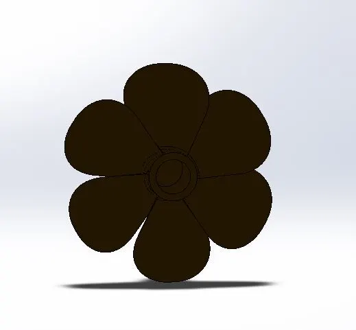
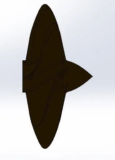
Propeller is used to propel the yacht, the propeller has blades on it and according to the angle of the blade the thrust force is created and this force created is used to propel the ship. Propeller is always super strong to provide better strength and also having good corrosion resistance.
Commands used
Major commands used to model a propeller is given below
- Line
- Circle
- Arc
- Fillet
- Extrude
- Chamfer
- Cut extrude
Images of propeller
RADAR
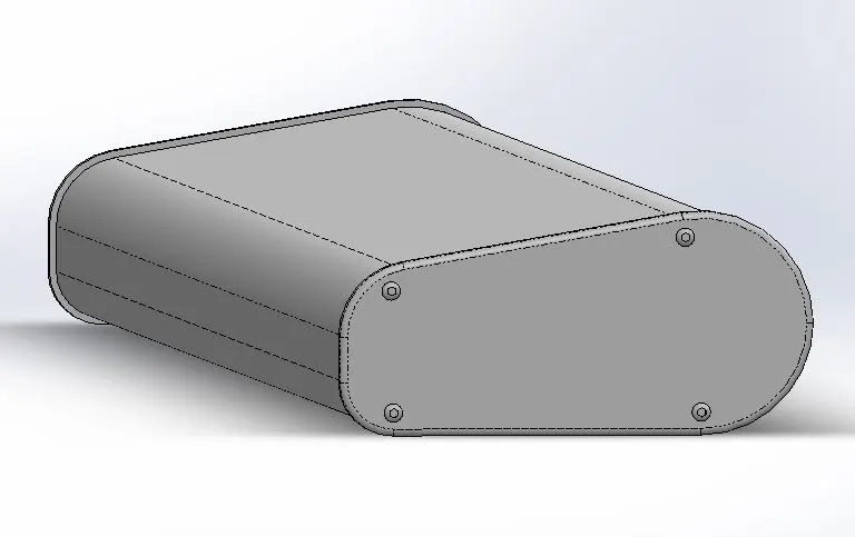
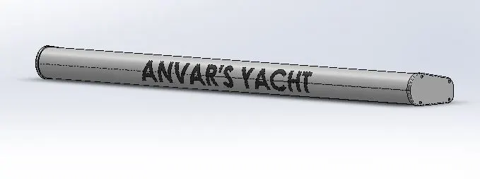
Radar is used to navigate the ship or yacht, and the signals received by the radar is transmitted to the yacht navigation systems and it is guided by the navigations system which is on the sea shore or any other maps used to navigate the yacht to a correct place.
Commands used
Major commands used to model a radar is given below
- Line
- Rectangle
- Boss extrude
- Cut extrude
- Fillet
- Chamfer
- Mirror
- Convert entities
- Offset entities
Images of the radar is shown below
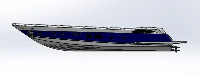
HULL
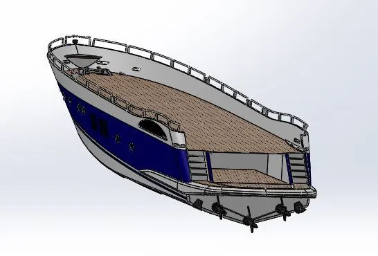
Hull is the main structure that is used to support the other structures such as superstructure, propeller, radar, etc. Hull is the basic structure of a yacht so it should be rigid and attractive. Hull contains support railings and other vehicle control systems and interior and exterior parts of that yacht, it is also having a large boot space which is bigger so it can adopt a car, so it will be luxurious and spacious.
Commands used to model a hull
The major commands used to model a hull is given below
- Spline
- Projected curve
- Surface loft
- Trim surfaces
- Shell
- Extrude cut
- Offset surface
- Revolve
- Chamfer
- Fillet
- Mirror
- Revolve cut
- Sweep
- Filled surface
Images of the modelled Hull is given below
GARAGE DOOR
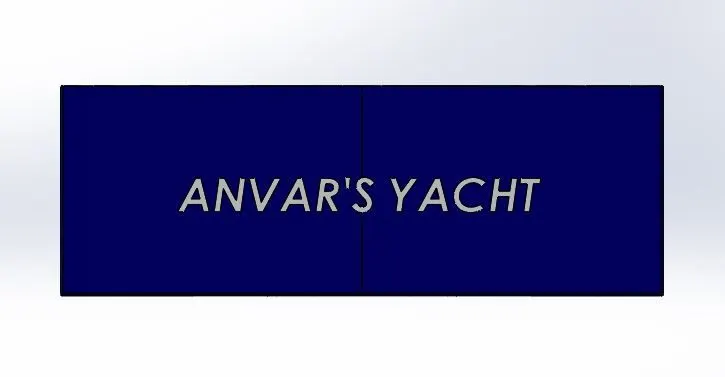
Garage door is used to open close the garage and it is a movable one and it should close and seal the area of the boot space area
Commands used to model Garage door
The major commands used to model this garage door is given below
- Line
- Spline
- Cut extrude
- Shell
- Split line
- Convert entities
- Offset entities
Images of the modelled garage door is given below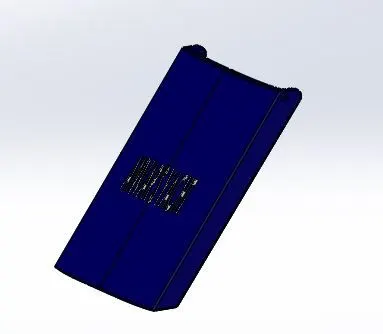
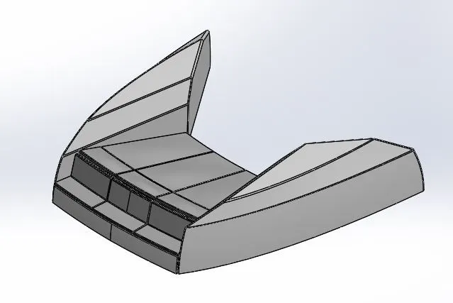
FRONT SEAT
Front seat is placed on the front side of the yacht and it is on the front side of the yacht and the front seat also has a luxurious seat on it.
Commands used
Major commands used to model this front seat is given below
- Spline
- Projected curve
- Surface loft
- Surface fill
- Boss extrude
- Cut extrude
- Revolve boss base
- Cut revolve
- Fillet
- Chamfer
- Surface offset
- Mirror
- Offset entities
- Convert entities.
Images of the front seat modelled is given below
REAR SEAT
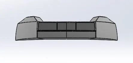
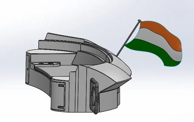
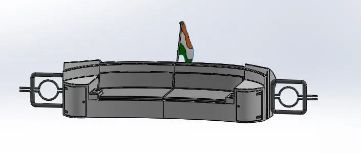
Rear seat is placed on the back side of the yacht and it is also having a flag on it and the rear seat also has various features on it to make it luxurious.
Commands used
Major commands used to model this rear seat is given below
- Spline
- Projected curve
- Surface loft
- Surface fill
- Boss extrude
- Cut extrude
- Revolve boss base
- Cut revolve
- Fillet
- Chamfer
- Surface offset
- Mirror
- Offset entities
- Convert entities.
The modelled rear seat images are given below
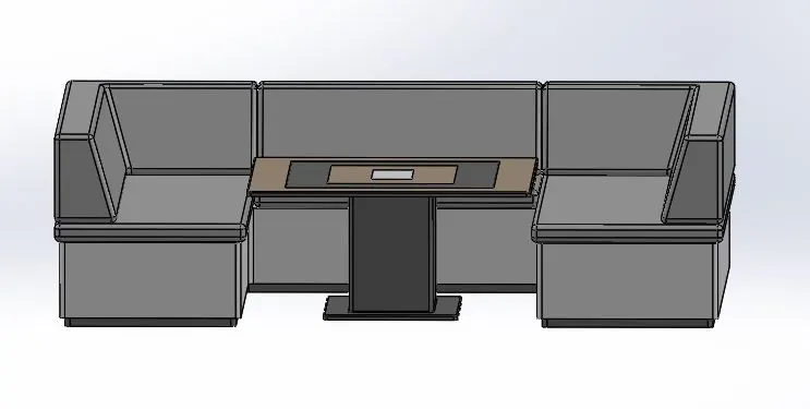
MIDDLE SEAT
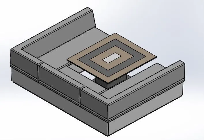
Middle seat is placed behind the superstructure back door area and the middle seat has the table arrangement with it, to make sure the seats are luxurious.
Commands used
Major commands used to model this rear seat is given below
- Spline
- Projected curve
- Surface loft
- Surface fill
- Boss extrude
- Cut extrude
- Revolve boss base
- Cut revolve
- Fillet
- Chamfer
- Surface offset
- Mirror
- Offset entities
- Convert entities.
The modelled middle seat images are given below
SUPER STRUCTURE
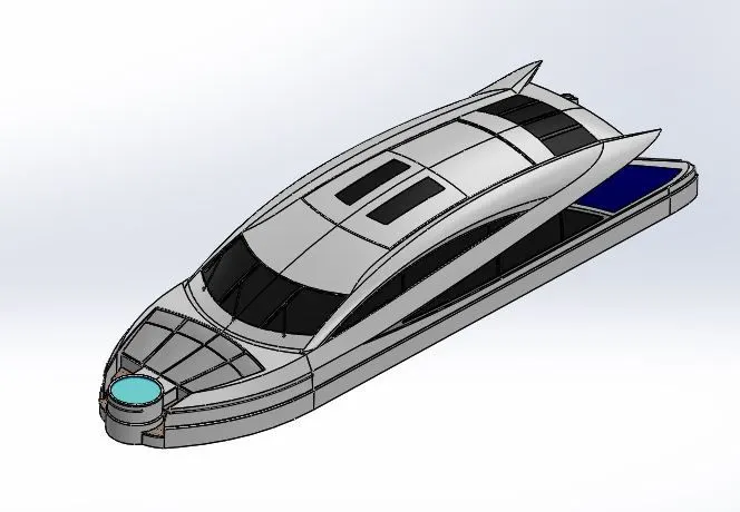
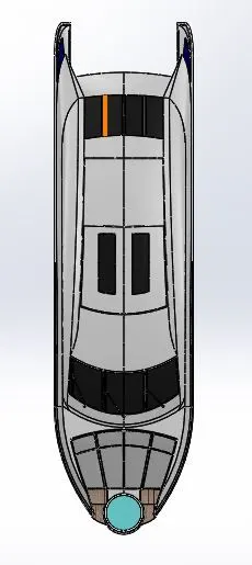
Super structure of the yacht supports various devices that is used to control the yacht and also it provides a good space for the passengers and this super structure is also having a good appearance, and a good aerodynamics quality to increase the stability and performance of the yacht.
Commands used
Major commands used to model this superstructure is given below
- Spline
- Projected curve
- Surface loft
- Surface fill
- Boss extrude
- Cut extrude
- Revolve boss base
- Cut revolve
- Fillet
- Chamfer
- Surface offset
- Mirror
- Offset entities
- Convert entities.
- Surface trim
- Surface extrude
- Surface extend
- Knit surface
- Surface sweep
- Delete face
- Fill surface
The modelled super structure images are given below
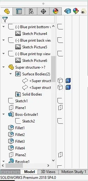
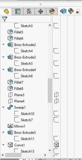
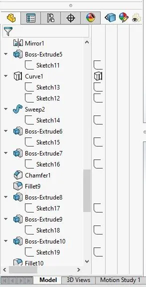
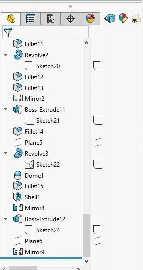
RADAR MAST
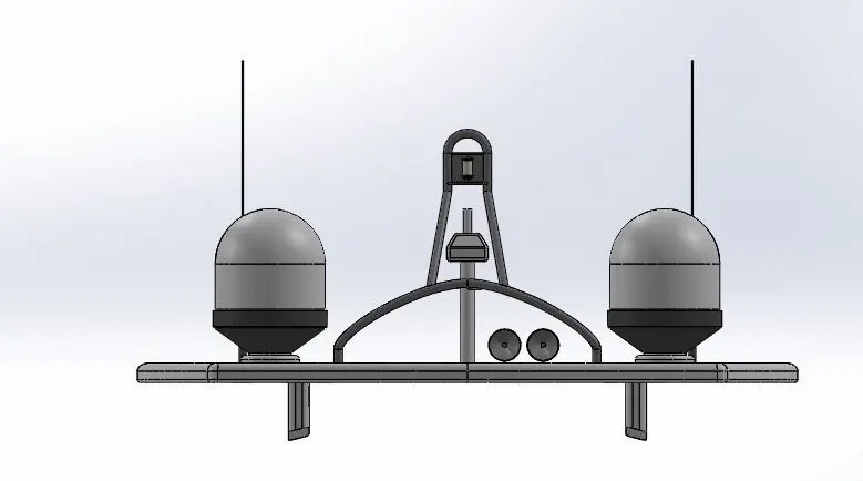
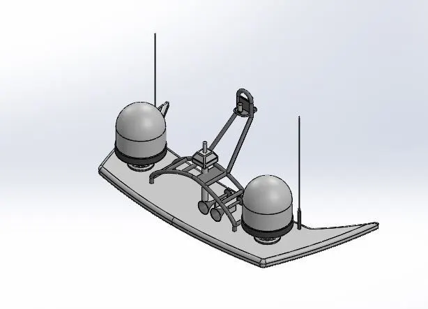
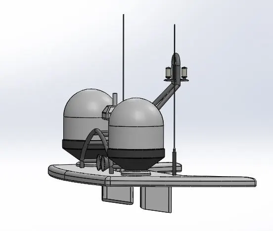
Radar mast is an assembly of several devices that supports the radar and the navigation systems and horns, lights and various devices that is used to navigate and control the yacht.
Commands used
The major commands used to model this radar mast is given below
- Spline
- Projected curve
- Boss extrude
- Cut extrude
- Revolve boss base
- Cut revolve
- Fillet
- Chamfer
- Surface offset
- Mirror
- Offset entities
- Convert entities.
The modelled radar mast images are given below
ASSEMBLY AND RENDERING OF PREDATOR YACHT
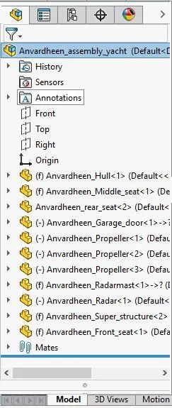
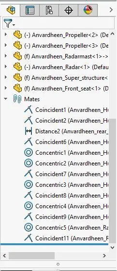
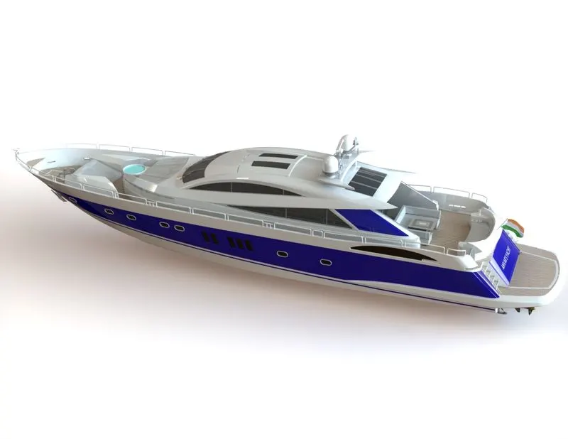
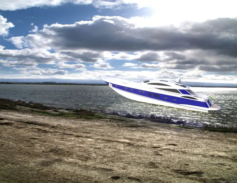
All the parts are imported in to the assembly environment using insert components command and appropriate mate relation is given between components such as concentric, coincidence, distance mates. After creating the final assembly, the rendering of the assembly is done with appropriate appearances using photo view 360, and various camera angles and lights are also added.
Assembled and rendered images are shown below
CONCLUSION
Thus the parts of sunseeker predator yacht is modelled and assembled using various commands and various mates, and appropriate appearance is also given and the photo realistic rendering also done using solidworks.