Photo Realistic Rendering
MODELLING AND RENDERING OF AMERICAN CHOPPER.
OBJECTIVE
The main objective is to create the model of the American Chopper bike, assembling and rendering it with appropriate appearance.
INTRODUCTION TO CHOPPER MODELLING
In this chopper modelling i have created each and every part of that chopper bike using various commands and various operation in solidworks. Modelling this chopper includes various commands and the various ways of execution for the same command. In assembly modelling also used various mates not only coincidence, concentric, distance mates but also some advance mates also. In rendering the photo realistic approach is given using photo view 360.
VARIOUS PARTS OF AMERICAN CHOPPER
1.Transmission belt
2.Kick stand
3.Front fender
4.Rear fender
5.Chain
6.Oil tank
7.Pedal
8.Front wheel
9.Rear wheel
10.Front fork
11.Chassis
12.Engine
13.Gas tank
Features/commands used
1.Sketch
Sketch is a command which is used to create the 2d outline of the part to be modelled according to the view. According to the view various sketch planes are used to create a sketch of the part by using various commands like line, circle, rectangle, arc etc. Sketching is the most important thing to create the 3d part, each and every sketch need to be constrained, under defined and over defined sketches may create errors.
2.Line
Line is a command which is used to create a line on a sketch. Line is a very basic tool used to create a 2d drawing. Various types of lines are used in solidworks they are mid-point line, tangent line, construction line etc.
3.Circle
Circle command is used to create a circle in solidworks. Here perimeter circle is another type of circle.
4.Rectangle
Rectangle command is used to make the different types of rectangle in solidworks, various types of rectangles are used, according to the designer’s ability to draw a component easily. some of the rectangle commands are three-point rectangle, corner rectangle, centre rectangle, etc.
5.Offset Entities
Offset command is used when we are in sketching environment, and this is used to copy the existing edge of an object or line or curve of a sketch to specified distance and direction.
6.Ellipse
Ellipse command is used to create ellipse with major and minor axis. This command is used here to create a kickstand in this chopper modelling series.
7.Convert Entities
Convert entities is used to convert the edge of a part to a sketch plane according to the view. Here the edge may be a cure or a line or it can be any geometry.
8.Spline
Spline command is used to create a line which has curves on it with control points and spline handles. We can add more control points to control a spline. This spline command is used to get a nice curvature.
9.Boss Extrude
Boss Extrude is a command which converts the 2d sketch into a 3d object or part. Extrude is a metal adding feature. This feature has various options on it, like mid plane extrude, draft, etc. These various options are used according to the necessity.
10.Cut Extrude
Cut Extrude is a command which is used to remove material from the 3d object. This extrude cut is also have various options like the extrude command.
11.Revolve
Revolve is also a metal adding command which add material according to one rotational axis or centre axis. This revolve feature is also having various options like selected contours, angle of rotation etc.
12.Revolve cut
Revolve cut is the feature which removes the material from a 3d object according to the sketch drawn and centre axis. This revolve cut is also has selected contour and other options.
13.Fillet
Fillet is a feature used to avoid the sharp edges of the part by making them rounded corners. fillet is given to avoid the damage made by the sharp edges of a component to other components or to persons handling the object.
14.Chamfer
Chamfer is another edge treatment process this will also produce safe corners when compared to sharp edges. Various types of chamfers are available here in solidworks. Chamfer can be provided by using distance by distance, distance by angle etc.
15.Projected Curve
Projected curve is a curve created by projecting two different 2d curves drawn on two different planes, the intersecting area of these two curves are created as a new curve.
16.Sweep
Sweep option is used to create a 3d part using a sketch and a trajectory. The 2d sketch and the trajectory (sweep path) drawn should be in different planes.
17.Loft
Loft option is used to create a sweep between two different sketches with a fine transition. We can create loft using guide curve, or centre curve options.
18.Dome
Dome is a feature used to create a rounded vault like structure on the selected flat circular face. It may be elliptical or non-elliptical dome and continuous dome on the filleted edges also.
19.Circular Pattern
Circular pattern is a feature used to create copy of the modelled part with controlled instances and angles according to the centre line. We can select geometric pattern in this circular pattern.
20.Linear pattern
Linear pattern is a feature used to create number of copy of the modelled part with controlled instances and linear distances. We can select number of rows and other options in this linear pattern.
21.Split
Split is a feature used to split a part in to different bodies with different possibilities, consume cut bodies can be used for various results. Split is a powerful tool which can use a face, surface or a single open sketch as a splitting tool.
22.Extrude surface
Extrude surface is a feature which helps to extrude the line drawn into a surface. surface is having no properties of mass defined and no thickness. And this extrude surface has various options on it which allows us to extrude the surface and also to make a capped end, and knit surface options in a single command.
23.Boundary surface
Boundary surface feature is used to make a surface with the selected lines or edges of a surface as a boundary region.
24.Knit surface
Knit surface feature is used to join all the surfaces drawn into a single surface it also joins and eliminates the gaps between the surfaces by joining the surfaces. This feature has various options on it such as try to make solid, this option enables us to make a solid out of surface.
25.Shell
Shell, as its name suggests shell command is used for shelling purpose. We can create internal shell for a closed body with the assigned thickness or we can also create a open face by selecting the faces during the shell command.
26.Lofted surface
This feature is used to create a surface by creating section curves and guide curves. These section and guide curves are used to make the lofted surface.
27.Combine
Combine is a command which is used to perform different operations between two solid bodies. We can add, subtract or intersect them to create a new component.
28.Dynamic Mirror
In this dynamic mirror feature we have to select a construction line which acts as a reference line for mirroring the drawn sketch. This command will actively mirror the sketches drawn.
29.Move copy
This command is used to move the created component in the 3d space. The proper coordinates for the movement of the part from one coordinate to another should be given correctly.
30.Appearance
The proper appearance helps to identify the component and it will make it more attractive. There are different types of appearance like chrome plated, painted, glass etc. We can use them to make the part more attractive. The appearance given to the part will gives a good result in final rendering.
Transmission belt
Description
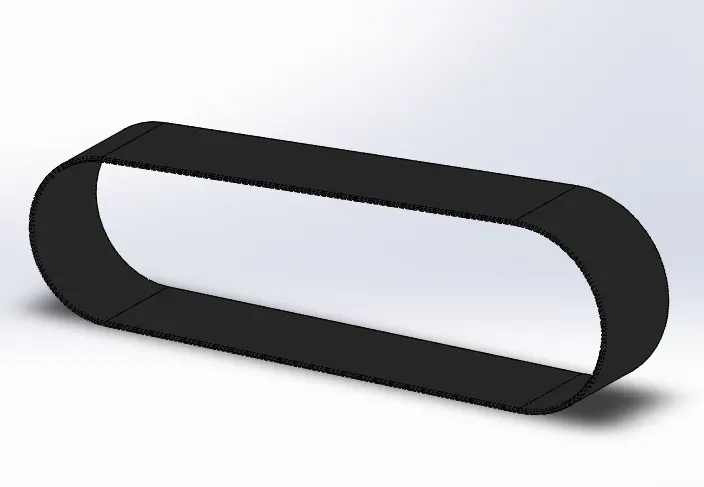
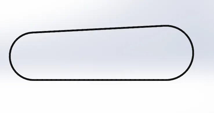
Transmission belt is a used to transfer the power from engine to gear box. Various types of transmission belts are available. These transmission belts are not only used in engines but also has a wide range of applications. Some of its types are v-belt, flat belt, toothed timing belts etc.
Commands used
Major commands used to model a transmission belt is given below
- Line
- Arc
- Extrude
- Fillet
Images of Transmission Belt
Kick Stand
Description
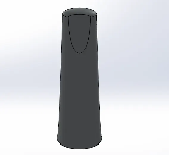
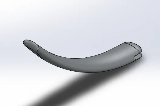
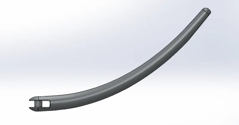
Kick stand is also known as side stand which is used to support the vehicle in a standing position with some inclination. Kick stand should be rigid and supportive. It is fixed using pin joint to make it functional.
Commands used
Commands used to model this kick stand is given below
- Ellipse
- Spline
- Loft
Images of Kickstand
Front Fender
Description
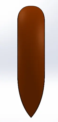
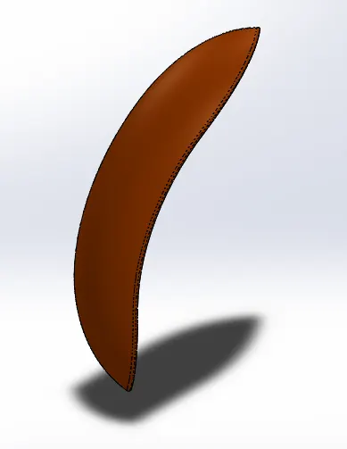
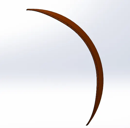
Front fender is a component of a chopper which works as a guard to prevent the vehicle and the passenger from mud and dust thrown by the wheel.
Commands used
Commands used to model this front fender is given below
- Arc
- Offset
- Revolve
- Split
Images of Front fender
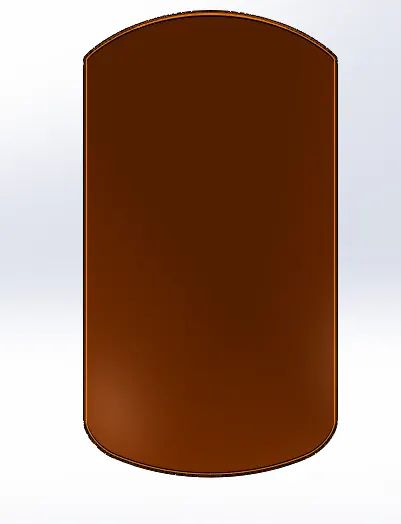
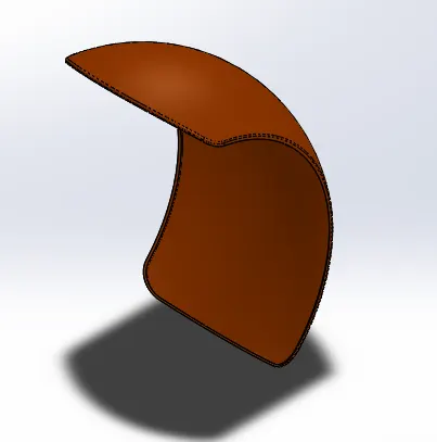
Rear Fender
Description
Rear fender is a component of a chopper which works as a guard to prevent the vehicle and the person who is travelling beyond the vehicle and the vehicle from mud and dust thrown by wheel.
Commands used
Commands used to model this rear fender is given below
- Arc
- Offset
- Revolve
- Shell
- Split
Images of rear fender
Chain
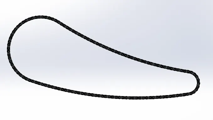
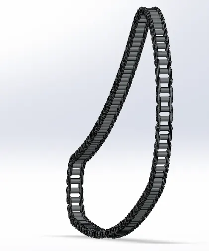
Chain is a component which transmits power. It is connected between the gear box output shaft and rear wheel. Usually bike has a chain drive system that transmits power to wheel, but some bikes use belt systems to transmit power.
Commands used
Commands used to model this chain is given below
- Sketch block
- Extrude
- Arc
- Curve pattern
- Fillet
- Mirror
Images of this modelled chain
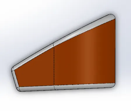
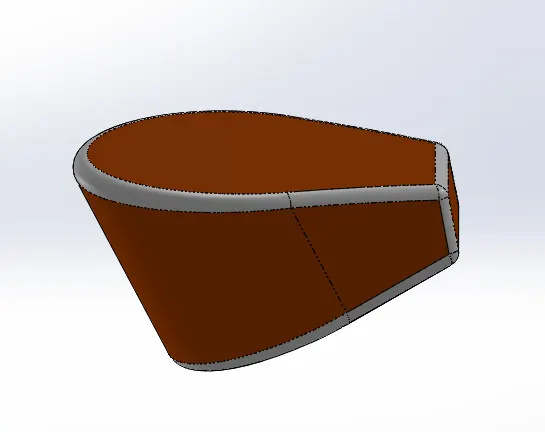
Oil tank
Oil tank is a reservoir which is used to store the oil. This oil tank supplies oil to the engine parts to avoid the wear and tear.
Commands used
Commands used to model this oil tank is given below
- Arc
- Line
- Extrude
- Combine
- Fillet
- Shell
Images of oil tank
Pedal
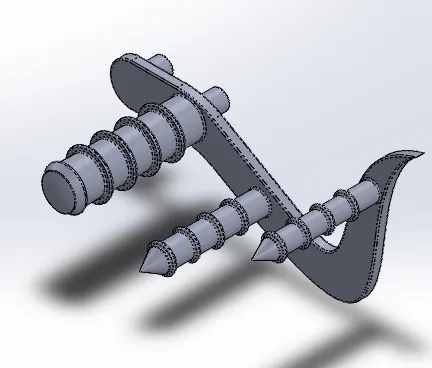
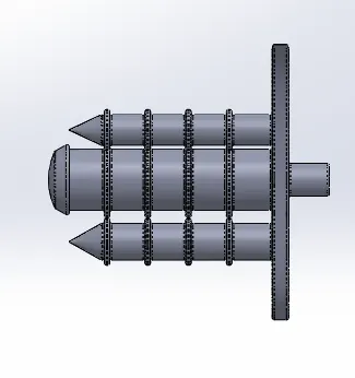
Pedal is a component which is used to rest our foot in a bike. And also it has gear leavers and brake leavers on it. Pedal should be rigid to hold the weight of the rider.
Commands used
- Sketch
- Spline
- Circle
- Fillet
- Chamfer
- Extrude
- Revolve
- Dome
- Linear pattern
- Convert entities
Images of pedal modelled
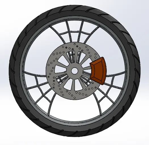
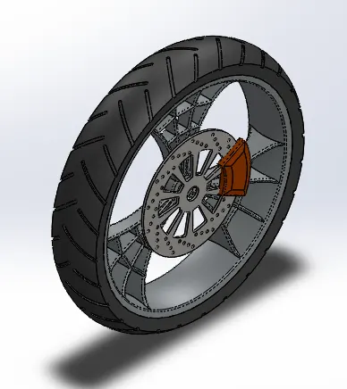
Front wheel
Wheel is a component used to move the vehicle by creating rolling motion and the wheel is connected to the hub by bearing. Wheel is also carrying brake rotor and other components. Tyre, brake, rim are the main components of wheel.
Commands used
Commands used to model the wheel is given below
- Revolve
- Convert Entities
- Circular pattern
- Linear pattern
- Boss Extrude
- Cut Extrude
- Offset
- Combine
- Fillet
- Chamfer
Images of front wheel modelled is given below
Rear wheel
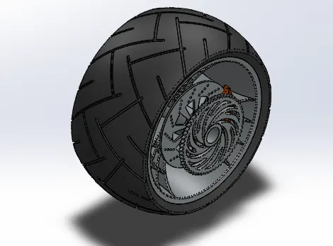
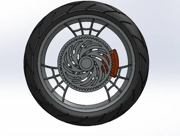
Rear wheel is a component used to move the vehicle by creating rolling motion and the wheel is connected to the hub by bearing. Wheel is also carrying brake rotor and other components. Tyre, brake, rim, sprocket are the main components of wheel.
Commands used
Commands used to model the rear wheel is given below
- Revolve
- Boss Extrude
- Extrude cut
- Fillet
- Chamfer
- Linear pattern
- Circular pattern
- Offset
- Convert entities
- Combine
Images of rear wheel modelled is given below
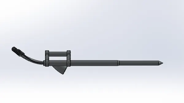
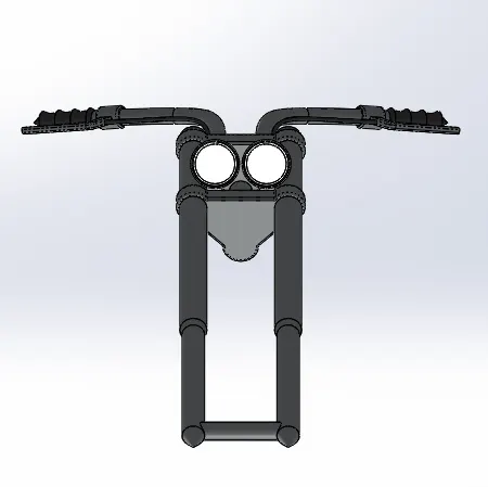
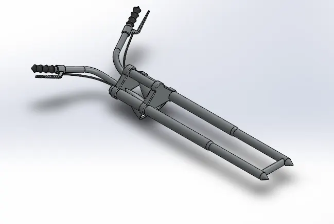
Front fork
Front fork is connected to the front side of the vehicle which allows us to steer the vehicle and also has various consoles to control the vehicle. Front fork has shock absorbers and brake lever to control the speed of the bike.
Commands used
Commands used to model the front fork is given below
- Sketch
- Revolve
- Mirror
- Projected curve
- Sweep
- Copy, move
- Boss extrude
- Cut Extrude
- Convert Entities
Images of front fork is given below
Chassis
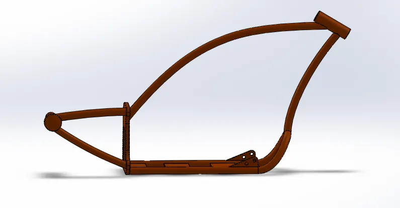
Chassis is the main structural component of any bike. It supports all other components of the bike and frame should be structurally rigid and in good shape to give a proper shape, and posture to a bike.
Commands used
Commands used to model the chassis is given below
- Sketch
- Project curve
- Sweep
- Combine
- Split
- Mirror
- Extrude
- Revolve
- Extrude cut
- Composite curve.
- Convert entities
- Fillet
- Chamfer
- Dome
Images of Chassis is given below

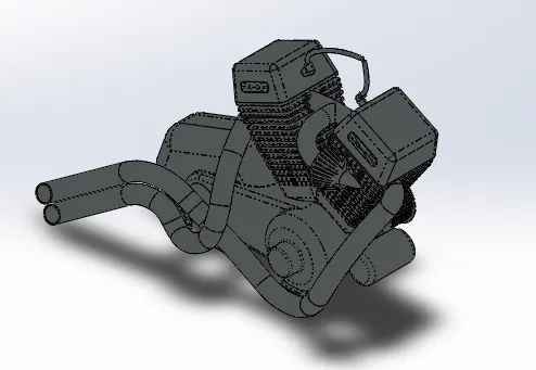
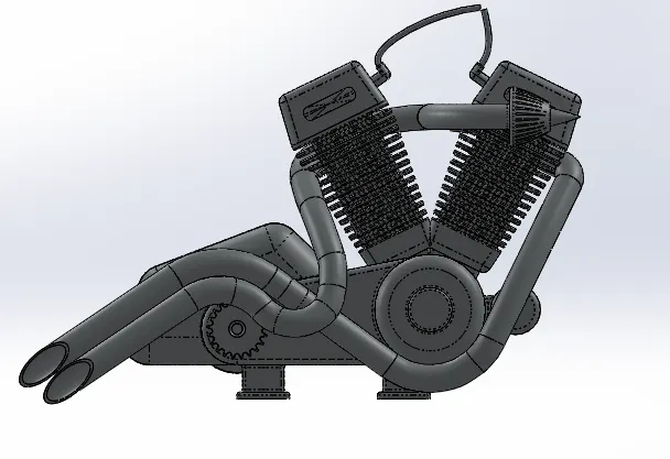
Engine
Engine is the major prime mover of a vehicle. Engine converts the heat energy into mechanical energy. Engine has many moving and stationary components inside it. Engine delivers power to the gear box, and gear box converts speed into torque according to the rider’s requirement. But engine produces some emissions while converting chemical energy to mechanical energy. Engine is the major reason for the development of world. Engine is developed over years and years, after that nowadays engine is not purely mechanical because engine is equipped with sensors and ECU (Engine control unit) which controls the intake, exhaust, temperature, power delivered, and controls the emission. Nowadays engines are replaced with electric motors, because of emissions created by engines and no any engine will provide 100% efficiency, most of the engines will give 50-60% efficiency only, but motors can produce above 90% efficiency.
Commands
Commands used to model engine is given below
- Sketch
- Extrude
- Fillet
- Chamfer
- Sweep
- Projected curve
- Extrude cut
- Revolve
- Cut Extrude
- Split
- Combine
- Circular pattern
Images of modelled Engine is given below
Gas Tank
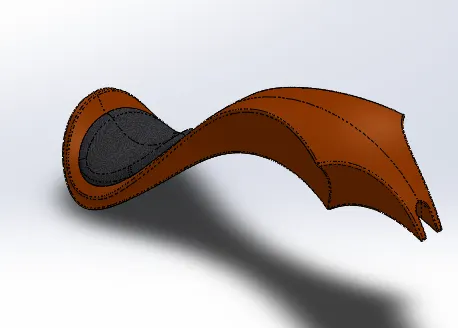
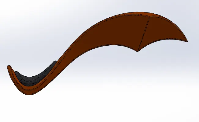
Gas tank is used as a reservoir for the fuel used in that vehicle. The shape of the gas tank will give a good appearance to the whole bike. Gas tanks are usually made up of sheet metal.
Commands used
Commands used to model a gas tank is given below
- Swept surface
- Boundary surface
- Loft surface
- Projected curve
- Knit surface
- Extrude Surface
- Fillet
- Chamfer
- Swept cut
- Shell
Images of modelled gas tank is shown below
Assembly and Rendering of American Chopper
Assembly of American Chopper
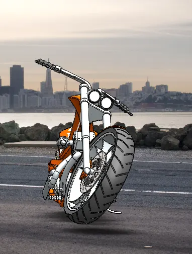
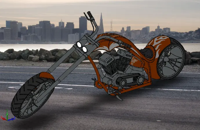
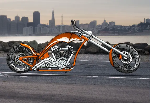
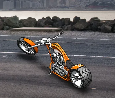
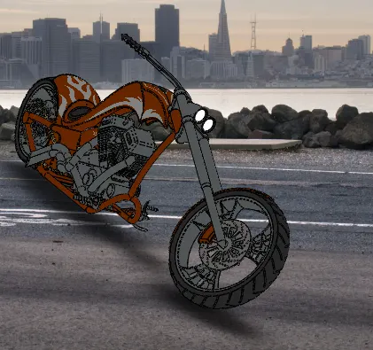
All the parts are imported to assembly environment using insert components command and appropriate mate relation is given between components such as concentric, coincidence, distance, parallel and some advance mate such as angle and width mate.
Assembled Images of the Chopper is given below
Rendering of the American chopper
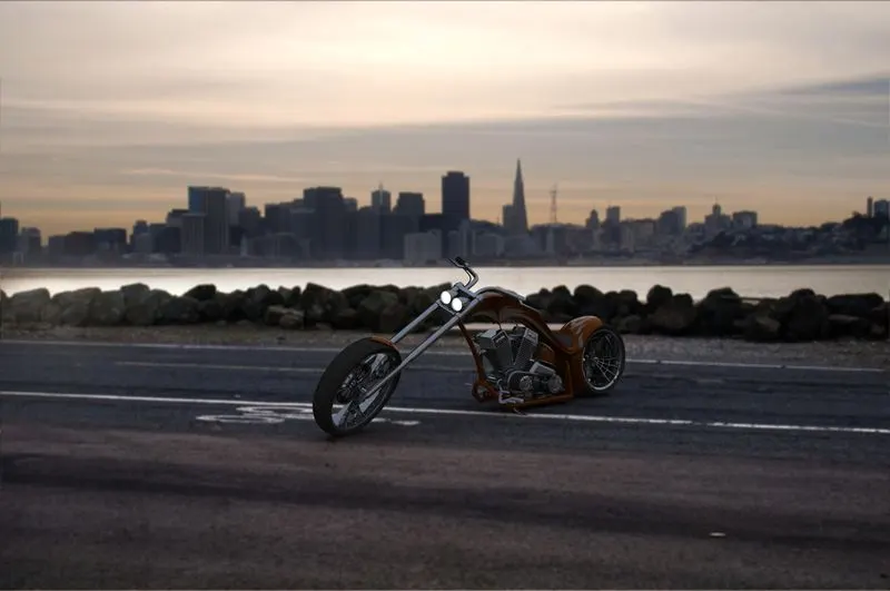
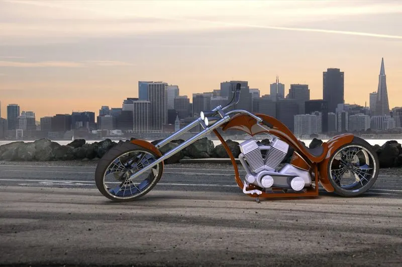
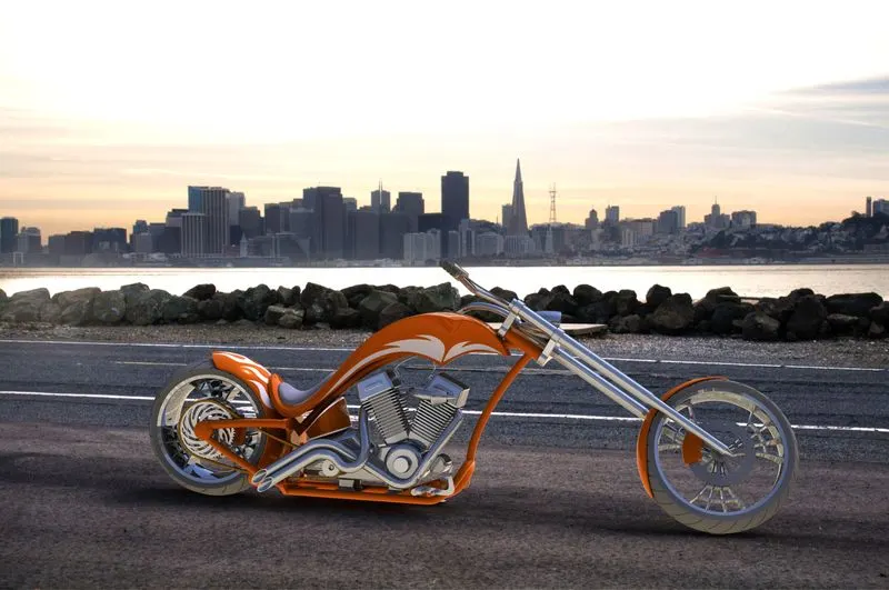
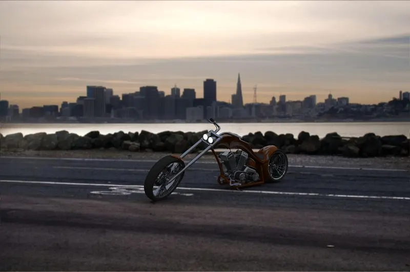
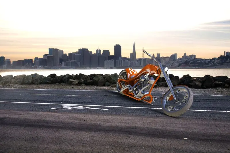
The Photo realistic rendering of the chopper is done by using photo view 360. Appropriate scene and lighting are applied. The camera angle is set properly and various options are fine tuned to provide a good rendering.
Rendered images are given below
Conclusion
Thus the parts of American chopper are modelled and assembled in solidworks using the above mentioned commands in this report and appropriate appearance are also given, and photorealistic rendering is also done using various light angles and light settings, camera angles and images of that rendering is also attached.