Week 8 - Challenge 2 - Base Bracket Design
DESIGN AND DRAFT ANALYSIS OF BASE BRCKET
OBJECTIVE
The main objective is to design the B-surface and C-surface for the given class A surface and to determine the tooling axis to perform draft analysis on the part.
DRAFT
First we need to know what is draft. Draft is the predetermined taper angle given with reference to the tooling axis. Tooling axis means it is the direction of the mold opening and closing or the direction of the ejection of the component from the injection moulding machine. The below image shows the draft given in a component.
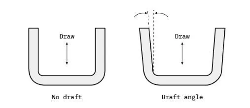
The above image shows the draft, every plastic part which have to be manufactured using injection moulding should have a draft. Giving a minimum draft angle of 3 degrees will helps to avoid the wear and tear in the core and cavity of moulds. This will help to increase the tool life, finally it will not only reduce the cost but also increases the surface finish quality of the plastic part produced by avoiding the scratching of the part along the faces of the mould.
Various draft angles are given according to the component, for plastic part 3 degree is given. For features in the injection moulding components like ribs etc., 0.5 degree is given, and 7 degree of draft is given for grinding surfaces like IP panel etc.
DRAFT ANALYSIS
Draft analysis is the tool used in CATIA to find out the draft given on the faces according to the main tooling axis, and as a result the CATIA will produce the colour codes which shows that the required draft is achieved or not. The detailed steps for achieving the draft analysis is given below.
Checking for gaps in the class A surface, all the areas of the class A surface should be joined without any gaps on it. We can check it using two ways by using the join command or by using the boundary command, for the join command we have to select the surface in the join command to see the boundary is created or not, this boundary is created when there is no gap in between the surfaces. In the another method of boundary creation there is no any open profiles in the final output and there should be only two domains after the disassemble of the boundary, reference pictures are shown here
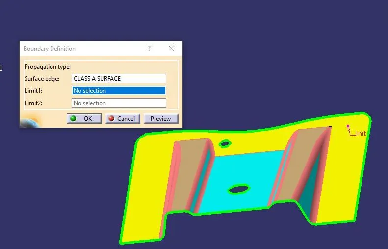
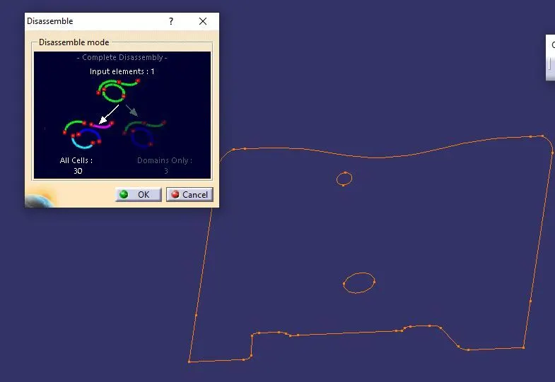
Boundary method is shown in the above images
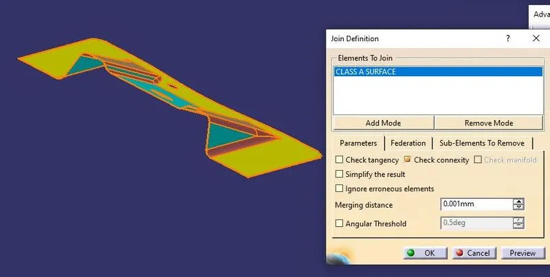
Join method is shown in the above image
After checking the class-A surface we need to check the proper axis for the dummy tooling axis, this tooling axis can lie on any one of the xy, yz, zx planes. For the below shown model the dummy tooling axis is created on the z direction. It is shown in the below image
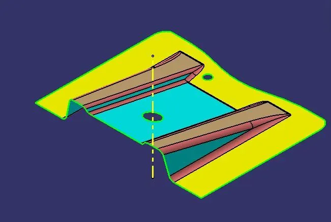
After creating dummy tooling axis we have to find the surfaces along the x or y directions which will make complications in the main tooling direction, in other words we have to solve the faces which are near parallel to the dummy tooling axis, and with the help of the line created on the problem creating surfaces we will create the tooling clearing x direction and tooling clearing y direction lines. In this case the slanting face which is shown in the x direction is near to perpendicular to dummy tooling axis so the tooling clearing x direction is neglected here, and we have to find the tooling clearing y direction only
Tooling clearing y direction
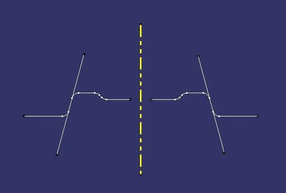
With the usage of the bisecting line command the tooling axis clearing y direction is created it is shown below
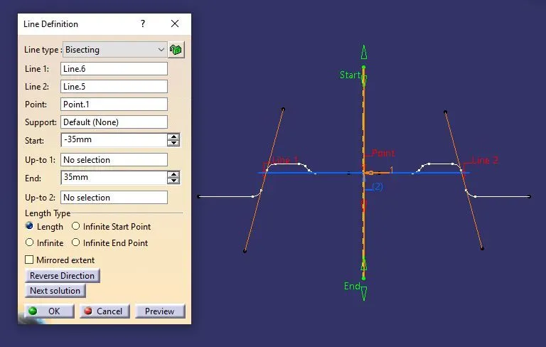
For the creation of bisecting line we have to select two lines that is drawn through two points on the reference faces and another point to create the tooling axis, here we have only tooling clearing in y direction only so this would be our Tooling axis.
Now with the help of the tooling clearing line y direction the tooling axis is created, this tooling axis is also known as main tooling axis.
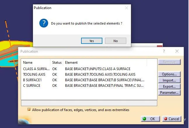
Then with have to publish the Class-A surface and Tooling axis for ease of access, we can find the publish icon on the TOOLS drop down publication icon.
After creation of the tooling axis we have to perform the draft analysis. For making draft analysis we need to give material mode for the part
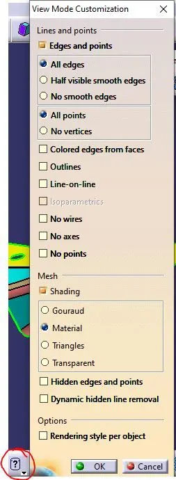
After entering into material mode we have to select the draft analysis on the insert dropdown analysis tab, in that draft analysis we have to select the compass icon shown on the Direction tab’s second icon and we have to place the compass from the screen and place it along the tooling axis.
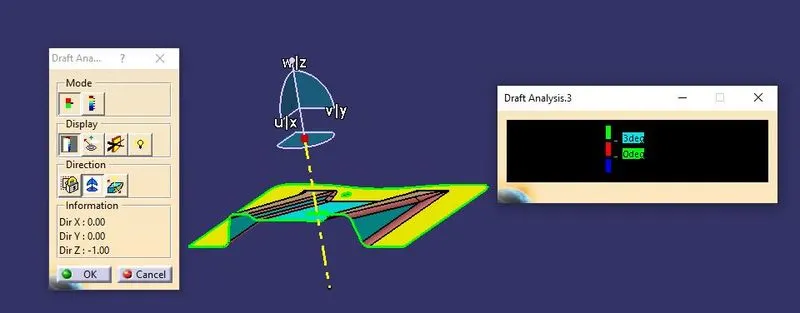
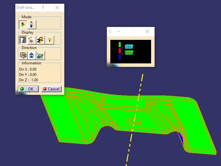
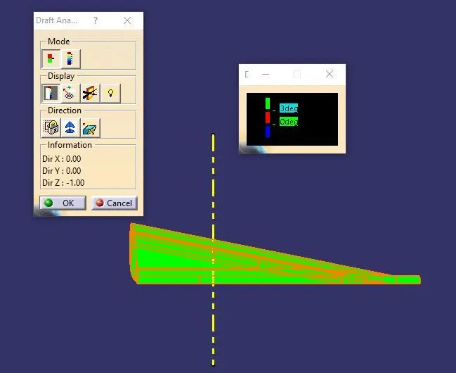
The colour code shows the draft given on that surface, the colour codes shown here of green colour is above 3degree draft, here the draft given on the surface is above 3 degree so the part is shown in green colour. If the draft is less than 3 degree it will be shown in red colour and if the draft is less than 0 degree then the part will be shown in blue colour.
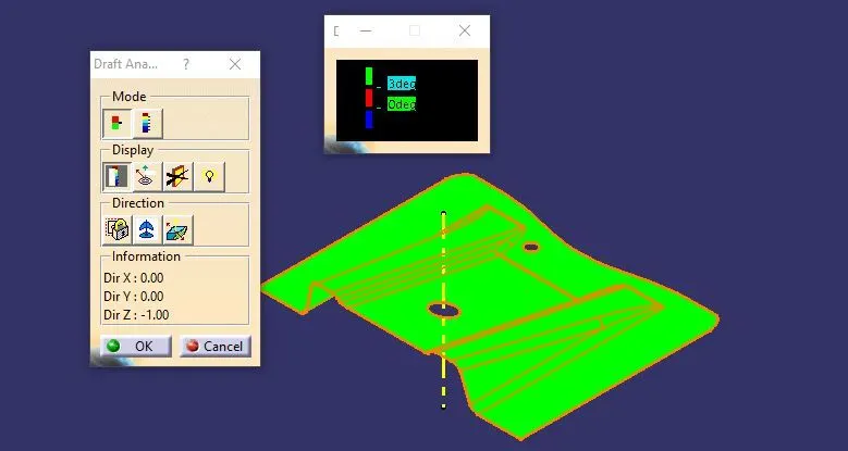
various views of the draft analysis is given below
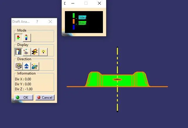
Below images shows the side view and top view of the draft analysis
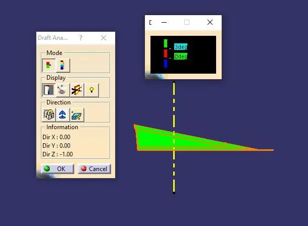
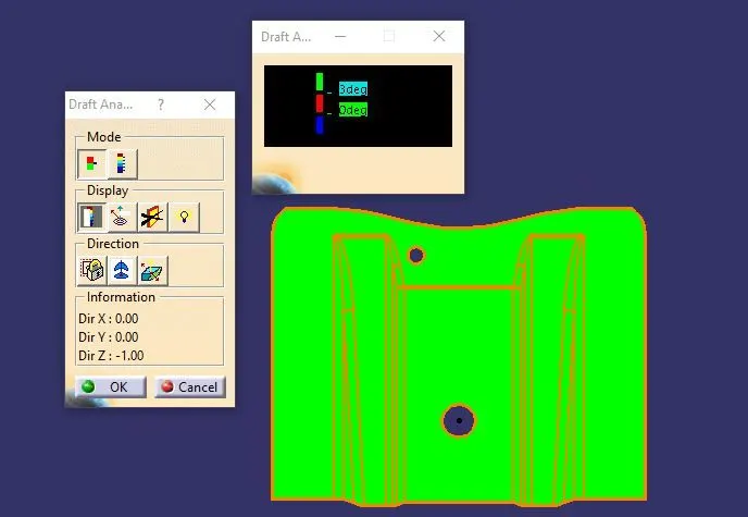
After making draft analysis we have to create the B-surface for the given class-A surface by using the following commands such as Extract, Un-trim, Extrapolate, for creation of the B-Side surface after creating the separate surfaces we have to make final Trim to create the complete B-side surface the offset value is the thickness of the component
The below images shows the created B-surface using the above commands, fillets and other features are also given in this B-surface
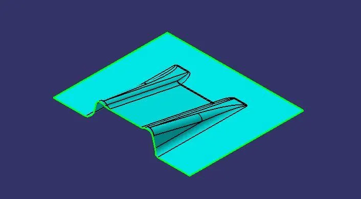
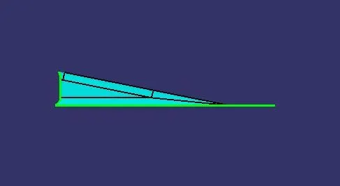
After creating the B-surface we have to create the c-surface to close the A and B surface and to form a closed surface model of the Base bracket.For the creation of the C-Surface we have to extract the outer and inner hole edges of the A-surface using boundary command as shown in the image
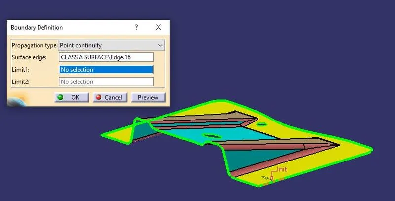
And we have to repeat the same steps for creation of the holes edges separately to create the C-surface
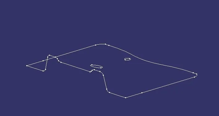
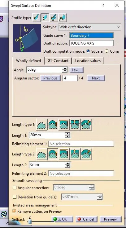
Then use the sweep command to form the c-side surface, and in sweep command use the second option(line) in the profile type and in sub type select the with draft direction, in guide curve select the boundary created by the sweep command and select the tooling axis in draft direction and also give adequate draft angle and direction to perform the sweep, it is shown in the below image
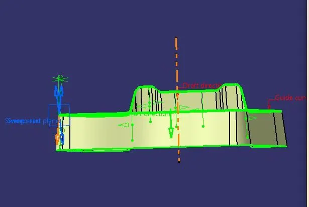
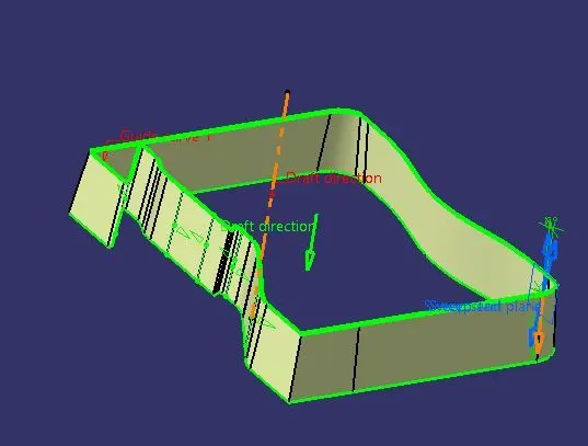
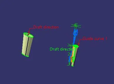
Also repeat the same steps for the hole’s C-surface creation
these created surfaces are separate surfaces we need to join the C-surfaces with A-surface
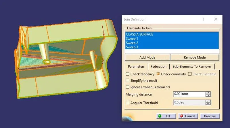
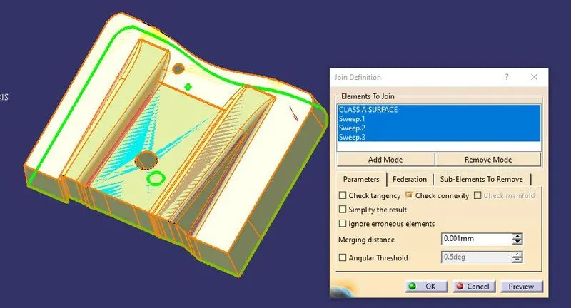
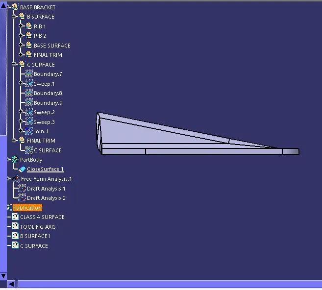
After joining the A-surface with C-surface we have to trim this join with the B-surface, after trimming it in the correct direction the closed surface model for the bracket is the created using surface commands, this closed surface is shown below
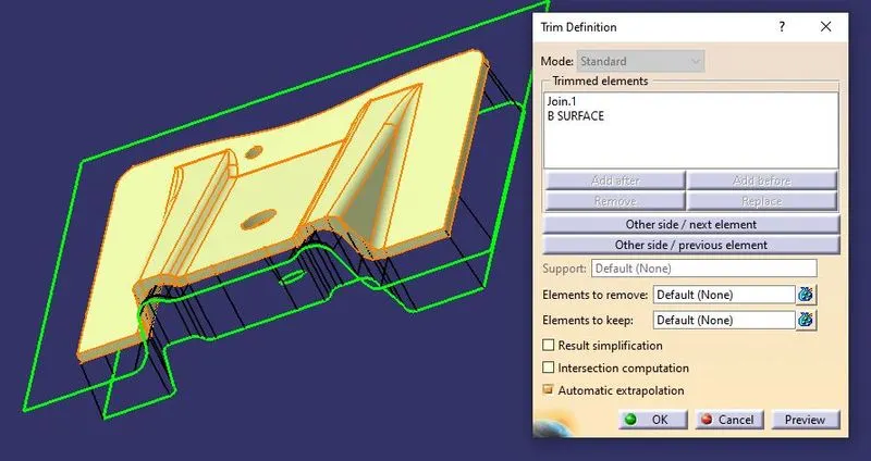
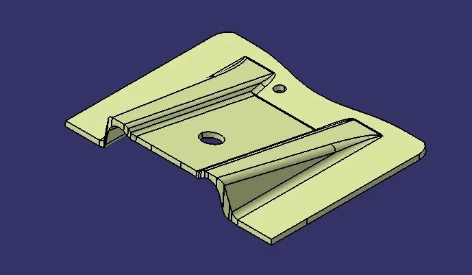
This closed surface model is used to create the complete part model by using the close surface command in the part workbench.
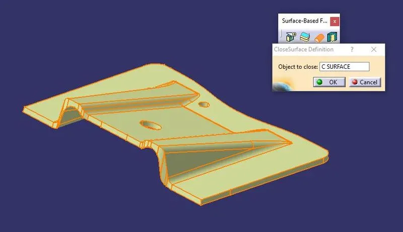
Once after creating the C-surface and the B-surface we have to publish them by using the Tools dropdown publication option same like what we did for the class-A and tooling axis publication.
Final draft analysis, we have to perform the final draft analysis for the created solid component to make sure it is manufacturable, do the same steps as shown in the above for the draft analysis of class-A, images are shown below
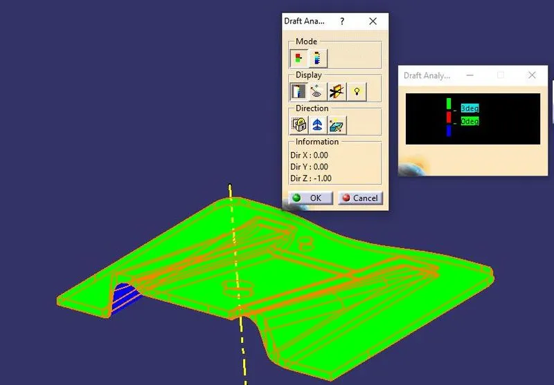
final part image is also given below
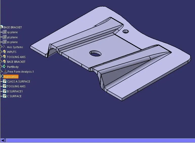
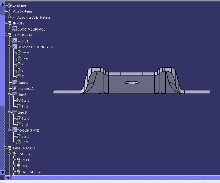
Thus the final solid part is created from the given class-A surface which can be manufactured and draft analysis is done.