Wiring harness routing & packaging Rules Week 3 Challenge
Q1. P Clamp Task:-To define electrical support using electrical part design
Ans-
Steps-1 Open igs file into catia
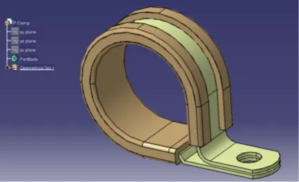
Step-2 Define geometrical parameters for P-clamp in Part design module with point (Circle, sphere option) & plane (choose plane through point)
Point should be at center. 3 planes & 2 points required to define its complete geometry
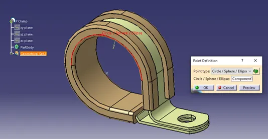
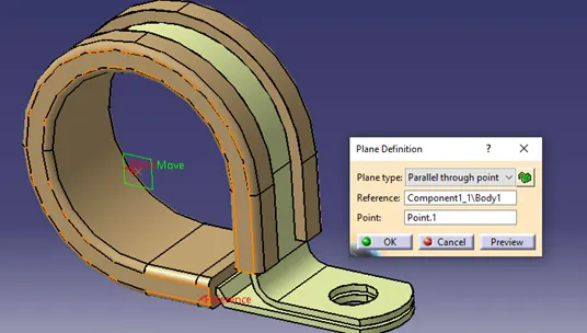
One side will be considered as entry side, then other side will be considered as exit side,
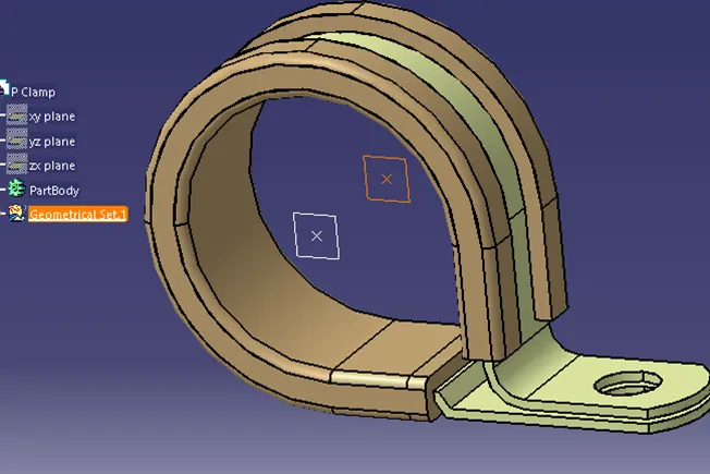
Step-3 Define point & plane on opposite side with same point & plane command, as shown in image below (for exit side)
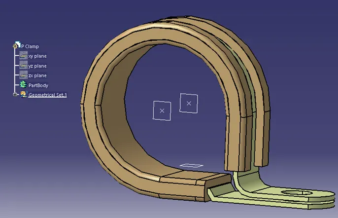
Step-4 Define base plane as shown in image below with 2mm offset from clamp surface
Step-5 Now to define as electrical support part switch into electrical part design module
Click on define support part command & click on clamp part geometry & then select point then plane of same point & then 2nd plane of opposite side & then select base plane as shown in image below
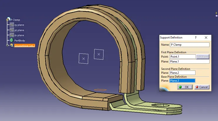
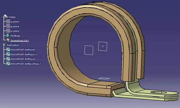
Step-6 Now to define other side, activate define support part command & click on clamp part geometry, then select other side point, plane of same point & plane 2 will be get selected by default, then select base plane
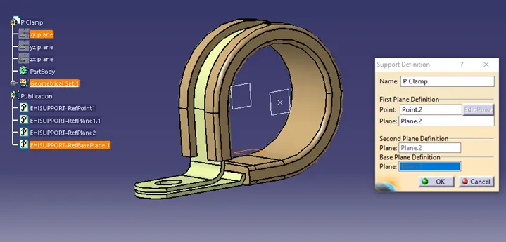
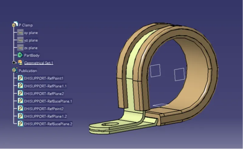
Now it has defined as electrical support part
Q2. Back Shell-Define it as Electrical back shell using Electrical Part design Workbench. Define all the necessary properties.
Ans-
Step-1 Open downloaded igs file in catia
Step-2 Define Geometrical parameters using in part design module with two points & axis system
First Define point at back shell connection point & other point at bundle connection point
Ensure both these point to be at center
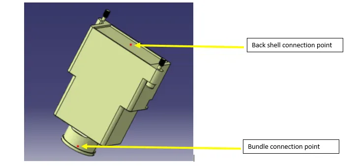
Step-3 Switch into electrical part design & click on Define back shell command & click on back shell geometry
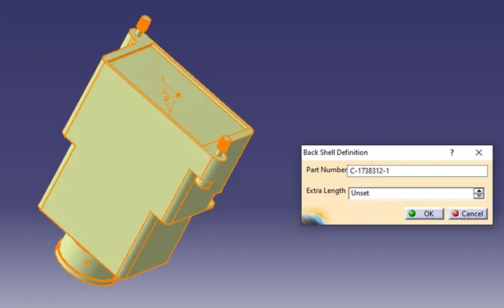
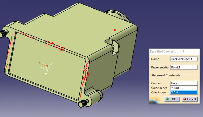
Step-4 Now click on Back shell connection point, then select point as representation, contact will be highlighted face in image, coincidence will be Y-axis & Orientation will be X-axis, then click OK
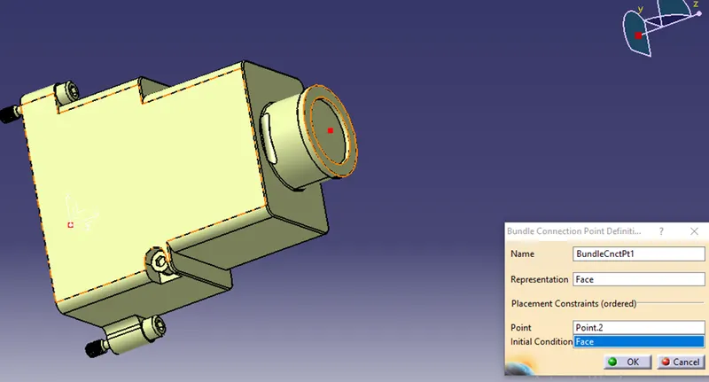
Step-5 Define bundle connection point with Define bundle connection point command
And select representation will be face , point as center point & initial condition will be highlighted face (Same face as selected for representation) & then click OK
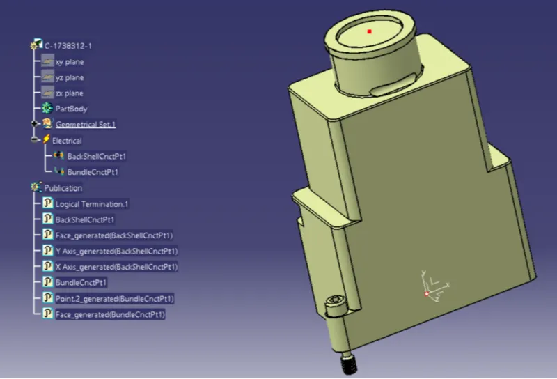
Thus we have defined Back Shell
Q3. Create Following Corrugated tubes & Add them in Catalogue under “Slit COT” family.
|
Name |
ID (mm) |
OD (mm) |
Thickness (mm) |
|
15mm COT |
12 |
15 |
1.5 |
Ans
- For 15mm COT- ID 12mm, OD 15mm, Thickness 1.5mm
Bend radius is .5 times of inner diameter i.e 18mm
Step-1 Create catalogue document with file-new-catalogue document & then add family & then name it as Slit COT (Family name) & in type select conduit for protective covering & save this catalogue document
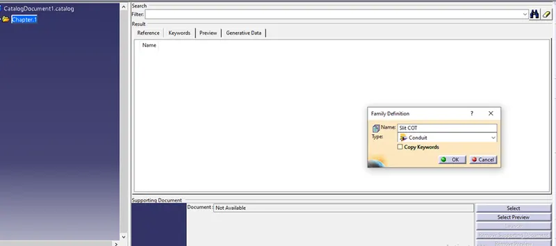
Step-2 In electrical part design module
Click on Define protection part command, then click on part & fill inputs, inner dia-12mm, thk-1.5mm & bend radius 18mm (Which is 1.5 times if inner radius)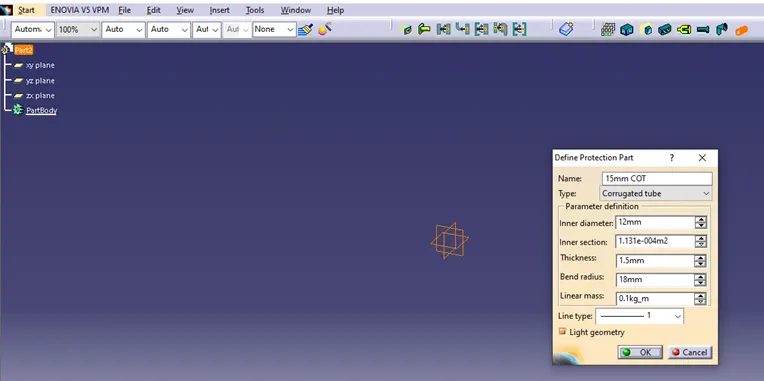
then click OK, result will be shown in image below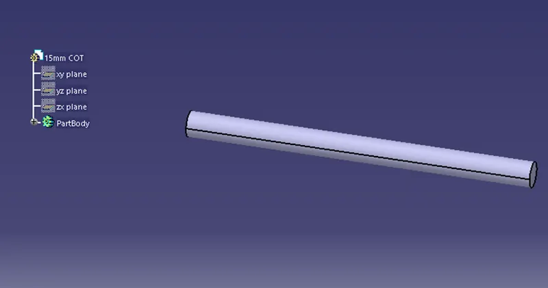
Step-3
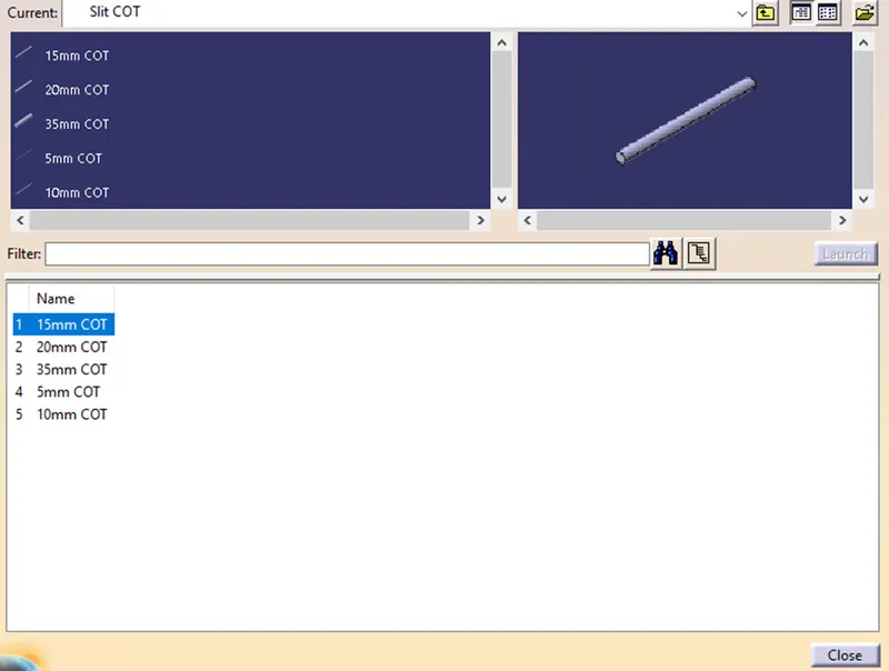
Click on store Device command & give the path of the created catalogue & family as Slit COT, check image below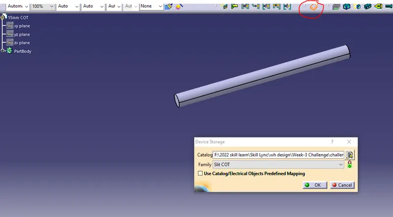
Like-wise follow the same steps for the other COT Tubes for different dimensions
- For 20mm COT- ID 17mm, OD 20mm, Thickness 1.5mm
Bend radius is 25.5mm
- For 35mm COT- ID 32mm, OD 35mm, Thickness 1.5mm
Bend radius is 48mm
- For 10mm COT- ID 7mm, OD 10mm, Thickness 1.5mm
Bend radius is 10.5mm
- For 5mm COT- ID 3 mm, OD 5mm, Thickness 1.5mm
Bend radius is 4.5mm
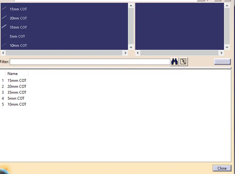
After creating all above COT tubes go to electrical harness assembly design & click on browse catalogue command then load Slit COT catalogue to view all COT tubes