Wiring harness design in CATIA V5 - 3D modeling Week 2 Challenge
- Connector code:- c-2-174357-2-e-3d
This connector has three bundle connection point
Follow the below Steps to define connector as electrical connector (Converting mechanical component into electrical device)
Step:-1 Open this connector into catia. Get it into part design module
Step-2 Define it’s geometrical parameters using point & axis system for both sides, connector connection side & bundle connection side
See below image
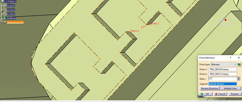
Step-3 Ensure axis systems in such a way that Y direction to be normal to connector side face & x-direction to be in locking side
See below image
Step-4 3 Ensure axis systems in such a way that Y direction to be normal to bundle connection side face & x-direction towards locking side
See below image
Step-5 Switch into electrical part design module
Step-6 Define connector by using define connector command and put number of terminals in number of termination tool box
See below image
Step-7 Define connector connection point using (Define connector connection point command), give specific inputs
See below image
Step-8 Define bundle connection point using bundle connection point command, give specific input, origin, contact face etc. see below image
- For Connector2 (C-dt06-08sa-b-3d) above same steps to be followed just by changing number of terminals points i.e. 8 Numbers to define connector as electrical connector
Now, to identify clip as equipment for assembly to the connector follow the below steps:-
Step- 1 Define geometrical parameters for clip (C-0085229-01-3) by opening it into part design module
Step-2 Point should be at the Centre of its connecting face, then define the axis in such a way that y-axis should be normal to its face and x towards it’s locking direction (Note:-This is not a standard practice, it is for understanding purpose)
Step-3 Then switch into electrical part design module
Step-4 Define clip as electrical equipment system
Step-5 Define cavity
Now, For assembly of clip & connector
Step-1 Connector & clip to be open in electrical assembly design
Step-2 make orientation proper with manipulation command in assembly design module
Step-3 Then from electrical assembly design use connect electrical device command to connect
Clip & connector