Wiring harness design in CATIA V5 - 3D modeling Week 7 Challenge
Title: Electrical Harness Flattening
Objective: To flatten the given Wiring Harness Assembly(Week 4 Challenge) using the Electrical Harness Flattening Workbench in Catia as well a creating a drawing of the flattened assembly.
Intrduction: CATIA - Electrical Wire Harness Flattening provides automatic and complete flattening of 3D Electrical Harnesses for manufacturing documentation in a concurrent engineering environment.
- Flattens bundle segments or electrical and geometrical bundles.
- Straightens bundle segments.
- Rotates whole bundle segments or bends them at a defined point.
- Rolls bundle segments.
- Scales bundle segments by introducing fake lengths.
Specifications:
Connectors:-
- DT06-4S
- DT06-6S
- DT06-2S
- DT06-08SA
Design Methodology:
- For Wiring Harness Assembly(Week4):
- Define all the connectors geometrically in Part Design Workbench.
- Define all the connectors electrically in Electrical Part Design Workbench.
- Create a new part document and create the desired routing layout using the line tool. We give the appropriate distance and angles to the lines.
- Start the Assembly Design Workbench in Catia and place the connectors in their appropriate places according to the given layout also rotate them into proper orientation.
- Now start the Electrical Harness Assembly Workbench. We convert the mechanical product into an electrical product by selecting the Geometrical Bundle option from the toolbars and then selecting the product name from the feature tree.
- Then we will create the branches to connect the different connectors with one another by selecting the Multi-Branchable Document option from the toolbars and the giving the values of branch diameter, bent radius, and slack% in the dialog box.
- After that we will click on the Route Defination option from same dialog box and then select the two connectors between which the branch is to be created. Click ok. We will repeat the same process for all the connectors.
- We will then add protective covering on all the branches connected to DT06-2S & DT06-4S connectors by selecting the Protective Covering option from the toolbars and then selecting the branch on which we want to add the covering and then browse for the required covering from the catalog browser option and then adding it to the branch. Click ok.
- Save the file.
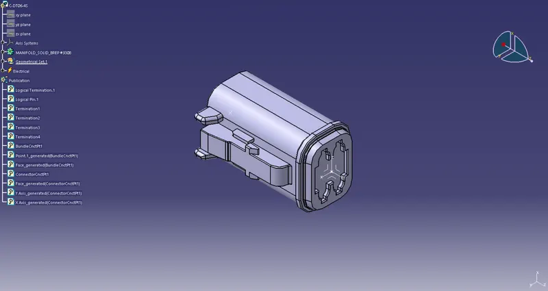
Fig1: Connector(DT06-4S)
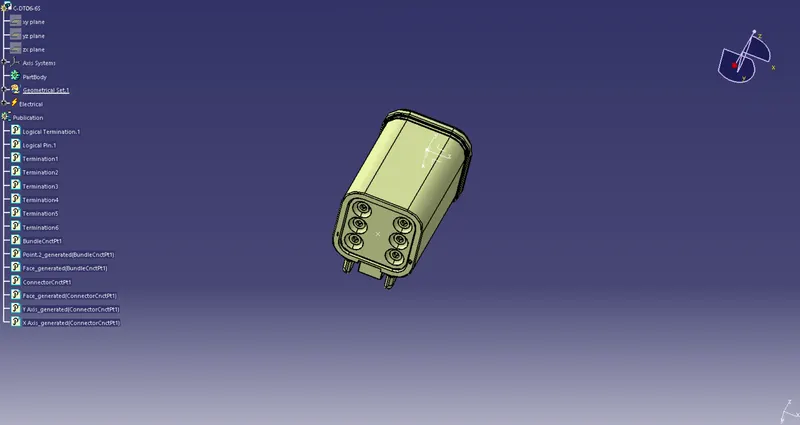
Fig2: Connector(DT06-6S)
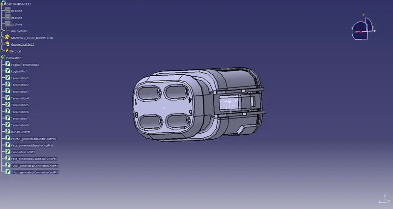
Fig3: Connector(DT06-08SA)
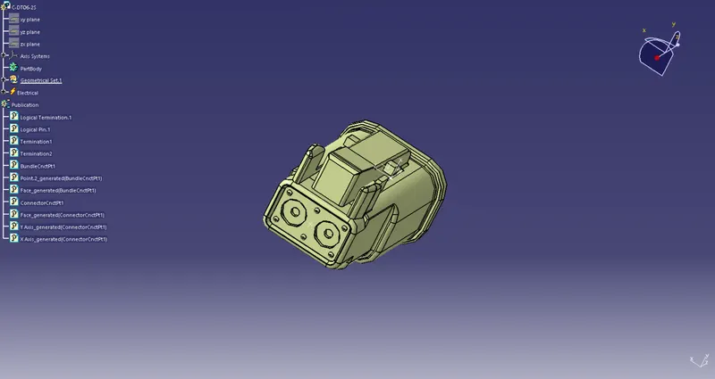
Fig4: Connector(DT06-2S)
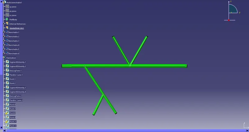
Fig5: Routing Layout
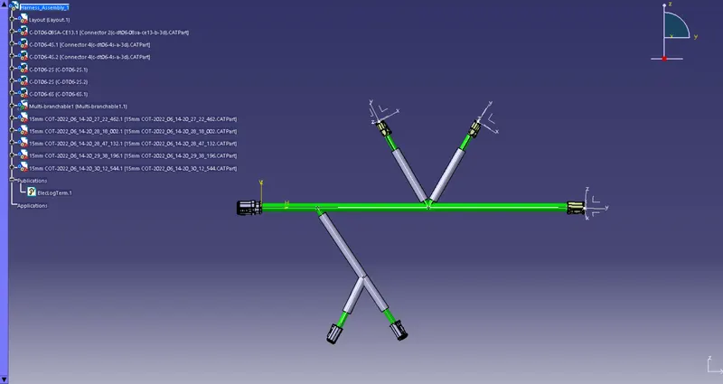
Fig6: Routing Assembly
- For Wire Harness Flattening:
1. Create a new product file in Catia
2. Start the Electrical Harness Flattening Workbench and select the Harness Flattening Parameters option from the toolbars.
3. A Harness Flattening Parameters dialog-box will appear and we have to set out our required parameters.
-
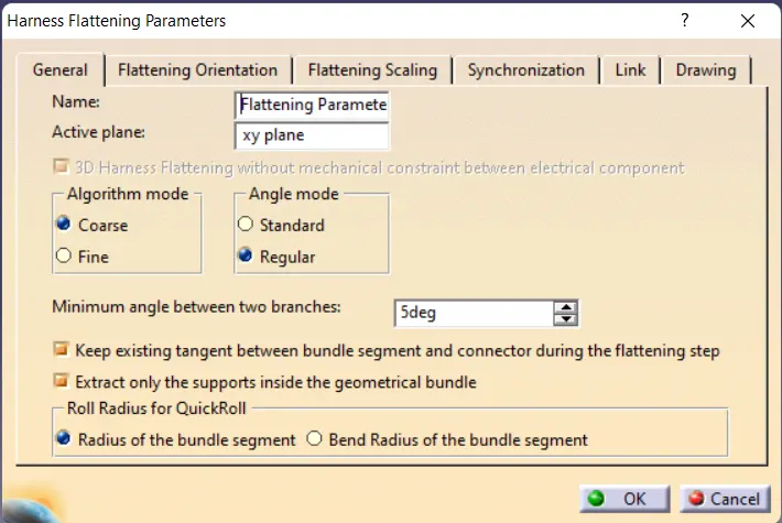
Fig7: Harness Flattening Parameters dialog-box
4. Then we have to open our previous product file of the Wiring Harness Assembly and then go to the Electrical Harness Flattening Workbench.
5. Select the Extarct option from the toolbars and then if our assembly is fully connected then the file gets extracted to the second product file. If our file fails to extract then that means that our assembly is not fully connected then in that case we have to redo and check our connections again.
6. After that we have to select the Flatten option from the toolbars and then select any face of our assembly with respect to which we want to flatten our assembly and then select all oue wire bundles and click ok. Our harness assembly then gets converted into a flattening assembly.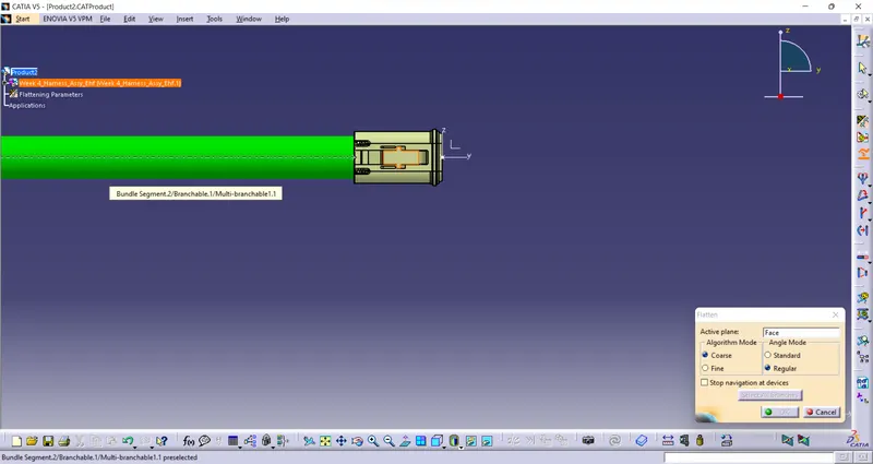
Fig8: Flatten Option7. Save the file in the same location as that of the Wiring Harness Assembly.
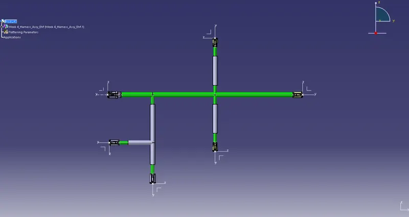
Fig9: Wiring Harness Flattening
iii. For creating the Flattening Product Drawing:
1. Create a new Drawing file.
2. Select the Front View option from the toolbars and then open the Wiring Harness Flattening window and select the same face that we had selected for our flattening.
3. The Flattening Assembly gets converted into a drawing file.
4. We add a tiltle box, bill of materials and annotations to the drawing.
5. Save the file.
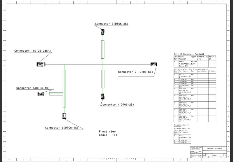
Fig10: Wiring Harness Drawing