Wiring harness design in CATIA V5 - 3D modeling Week 5 & 6 Challenge
Title: Wiring harness design in CATIA V5
Objective: To route the given harness layout in Electrical Assembly Workbench and after completion of routing, we:
- Check the bundle Continuity.
- Add annotation to all connectors.
- Check for the bundle warning if any.
- Generate CAT. Part of harness assembly and convert it in .igs format.
Design Methodology:
Routing the harness assembly:
- First open the 3D CAD data of all the connectors in Catia and then convert the file formats (ex: .igs,.stp) to .CAT Part.
- Define the connectors both geometrically and electrically with the help of the appropriate workbenches.
- Create two different assemblies called as Wire Harness A and Wire Harness B in the Electrical Harness Assembly Workbench and route the connectors according to the given layouts for both the assemblies.
- Now create a third assembly called wire Harness Assembly AB and then link Wire Harness A and Wire Harness B together electrically in the Electrical Assembly Design Workbench.
- Save the file.
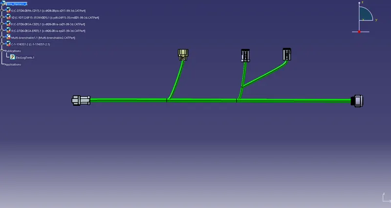
Fig1: Wire Harness A
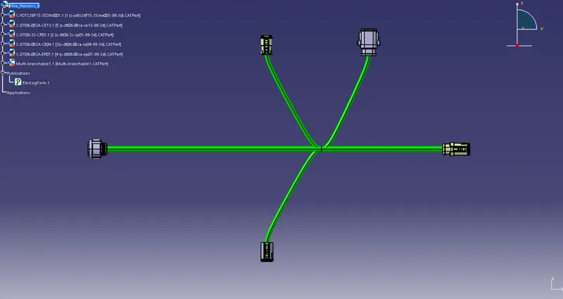
Fig2: Wire Harness B
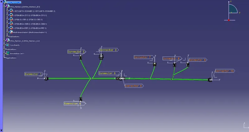
Fig3: Wire Harness AB
Checking the bundle Continuity:
- In Harness Assembly AB window go to Edit and then click on the Search option (or press ctrl + F) to open the search menu.
- In the menu select the Advanced tab and then select Electrical as Workbench, Bundle Segment as Type and fully connected as Attribute, a pop-up dialog box will appear, click on false to check whether there is any discontinuity in the assembly and the click on the search icon from the menu.
- A display will appear showing 0 object found which will ensure that our assembly is full connected and there is no discontinuity in any of the bundle segments.
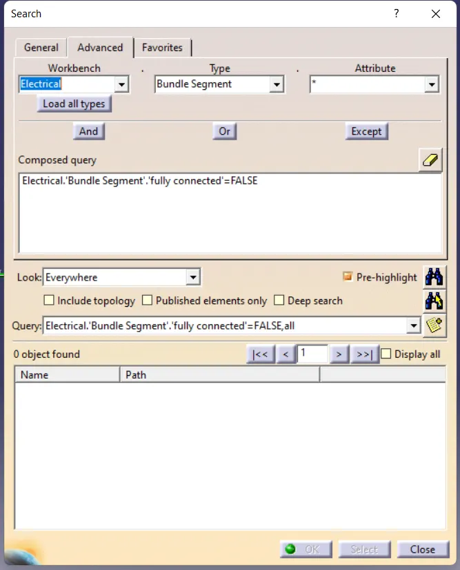
Fig4: Search Dialog Box
Adding annotations to all connectors:
- Go to Assembly Design Workbench and select the Front View/Annotations Plane Option from the toolbars and then select the any front plane of the connectors where we want to add the annotation.
- After that select the Flag Note with Leader option and the annotation will be added. Double Click on the annotation to give it a desired name.
- Repeat the same process for all the other connectors.
Checking for bundle warnings:
- No bundle warnings occurred.
Generating CAT. Part of harness assembly and convert is in .igs format:
- Lastly, we convert our CAT. Product file to CAT. Part file by selecting Tools > Generate CATPart from Product option and then our file gets converted and saved.
- We then use the Save As option to convert our file in .igs format.
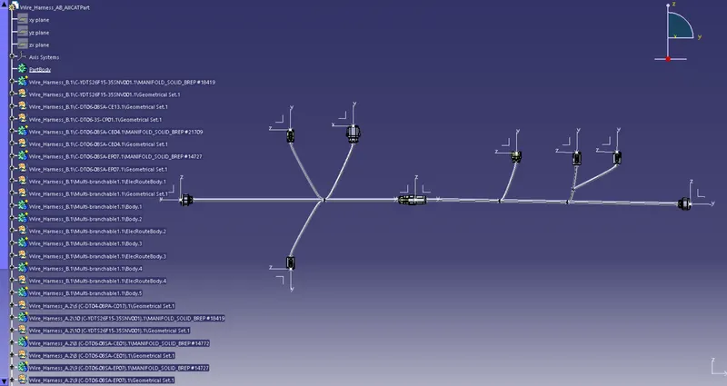
Fig5: Converted CAT Part from CAT Product