Photo Realistic Rendering
Title: Design and Assembly of an American Chopper Model
Objective:
To create the various different parts of an American Chopper bike and then assembling them together in SolidWorks as well as creating the final photo-realistic images of the chopper after rendering them with the help of Photo View 360.
Introduction:
This bike model is inspired by the popular American television series American Chopper where a group of specialists build and customize some of the most innovative motorcycles for various celebrities and enthusiasts.
In this report we will have a look at the various tools and features used to design the American Chopper model as well as take a look at the final rendered images of the model.
Design Methodology:
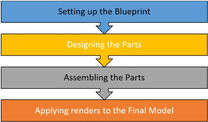
Fig1: Flowchart of the design approach
Design Process of the American Chopper Model:
The steps used for designing the model are as follows: -
- Setting up the chopper blueprint inside of SolidWorks.
- Designing the different parts of the bike.
- Setting up the chopper blueprint inside of SolidWorks.
- Assembling them together inside of SolidWorks assembly.
- Rendering the final assembly model to create photo-realistic images of the bike with the help of SolidWorks Photo-View 360.
The various different parts used for the assembly of American Chopper model are as follows:
- Transmission Belt
- Kickstand
- Front Fender
- Rear Fender
- Oil Tank
- Pedal
- Chain
- Front Wheel
- Rear Wheel
- Front Fork
- Chassis
- Engine
- Gas Tank
Tools and features used for designing the parts:
- Transmission Belt:
1.1. Boss-Extrude
1.2. Fillet
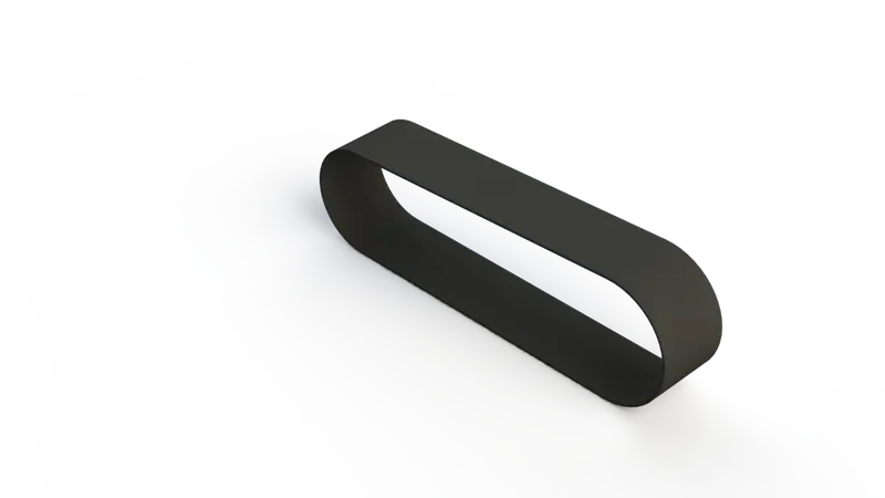
Fig2: Transmission Belt
- Kickstand:
2.1. Loft
2.2. Dome
2.3. Cut-Extrude
2.4. Boss-Extrude
2.5. Fillet
2.6. Split tool
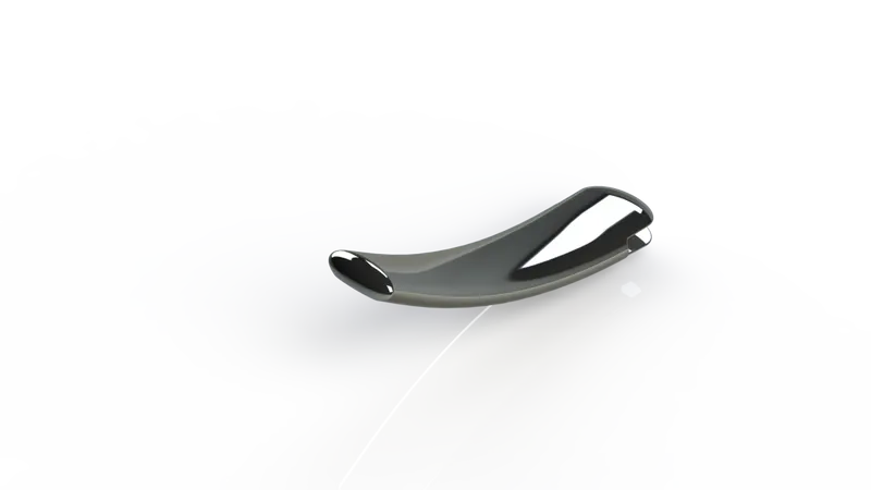
Fig3: Kickstand
- Front Fender:
3.1. Revolve
3.2. Split tool
3.3. Fillet
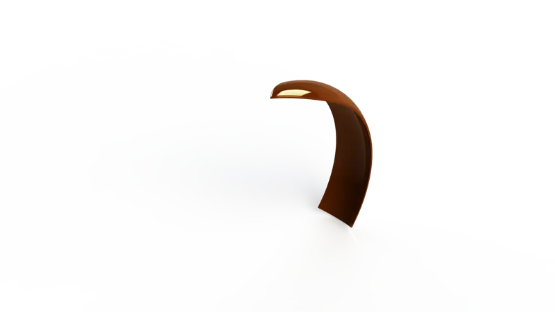
Fig4: Front Fender
- Rear Fender:
4.1. Revolve
4.2. Split tool
4.3. Fillet
4.4. Shell feature
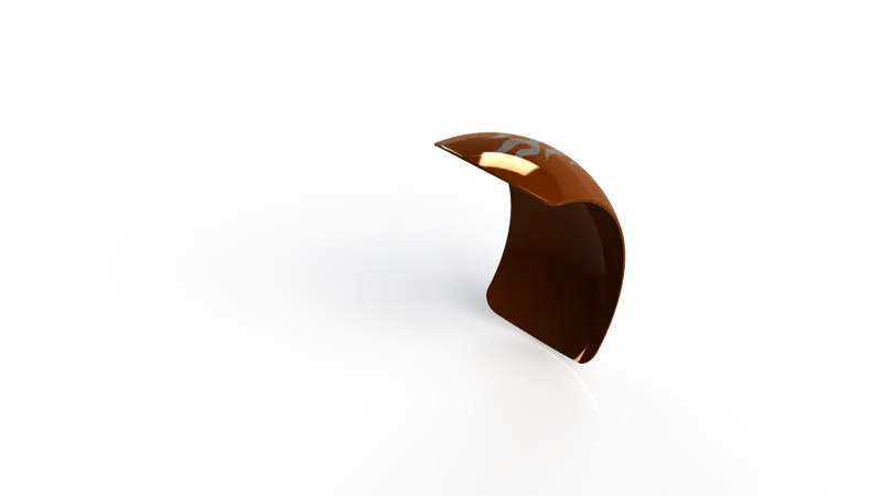
Fig5: Rear Fender
- Oil Tank:
5.1. Boss-Extrude
5.2 Combine tool
5.3. Fillet
5.4. Shell feature
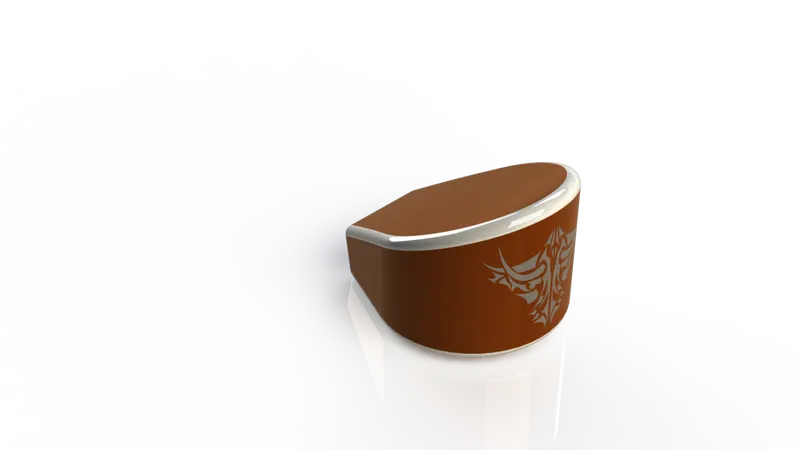
Fig6: Oil Tank
- Pedal:
6.1. Boss-Extrude
6.2. Fillet
6.3. Revolve
6.4. Dome
6.5. Chamfer
6.6. Linear Pattern
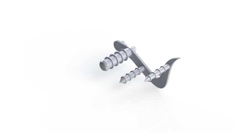
Fig7: Pedal
- Chain:
7.1. Boss-Extrude
7.2. Fillet
7.3. Block making
7.4. Circular Pattern
7.5. Mirror tool
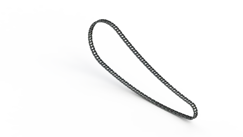
Fig8: Chain
- Front Wheel:
8.1. Revolve
8.2. Boss-Extrude
8.3. Cut-Extrude
8.4. Cut-Revolve
8.5. Circular Pattern
8.6. Combine tool
8.7. Fillet
8.8. Chamfer
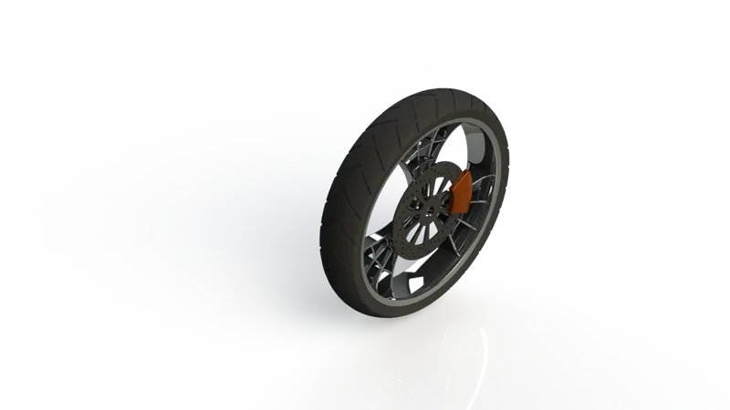
Fig9: Front Wheel
- Rear Wheel:
9.1. Revolve
9.2. Boss-Extrude
9.3. Cut-Extrude
9.4. Cut-Revolve
9.5. Circular Pattern
9.6. Combine tool
9.7. Fillet
9.8. Chamfer
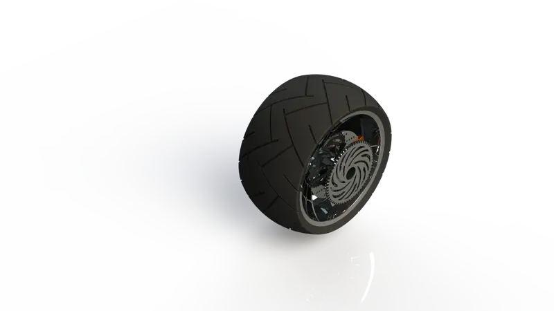
Fig10: Rear Wheel
- Front Fork
10.1. Revolve
10.2. Boss-Extrude
10.3. Cut-Extrude
10.4. Linear Pattern
10.5. Fillet
10.6. Combine tool
10.7. Swept-Boss
10.8. Mirror tool
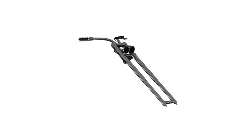
Fig11: Front Fork
- Chassis
11.1. Projected Curve
11.2. Composite Curve
11.3. Mirror tool
11.4. Swept-Boss
11.5. Boss-Extrude
11.6. Cut-Extrude
11.7. Chamfer
11.8. Fillet
11.9. Dome
11.10. Split tool
11.11. Combine tool
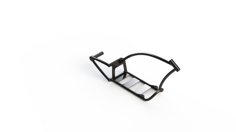
Fig12: Chassis
- Engine:
12.1. Boss-Extrude
12.2. Projected Curve
12.3. Composite Curve
12.4. Mirror tool
12.5. Linear Pattern
12.6. Circular Pattern
12.7. Swept-Boss
12.8. Boss-Extrude
12.9. Cut-Extrude
12.10. Chamfer
12.11. Fillet
12.12. Dome
12.13. Split tool
12.14. Combine tool
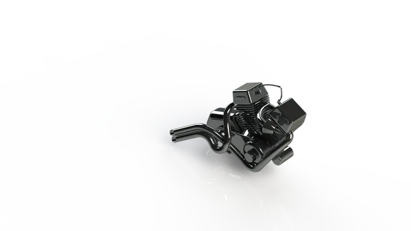
Fig12: Engine
- Gas Tank:
13.1. Surface-Sweep
13.2. Surface-Trim
13.3. Surface-Loft
13.4. Projected Curve
13.5. Composite Curve
13.6. Boundary-Surface
13.7. Mirror Tool
13.8. Surface-Knit
13.9. Split Line tool
13.10. Surface-Extrude
13.11. Cut-Sweep
13.12. Fillet
13.13. Shell
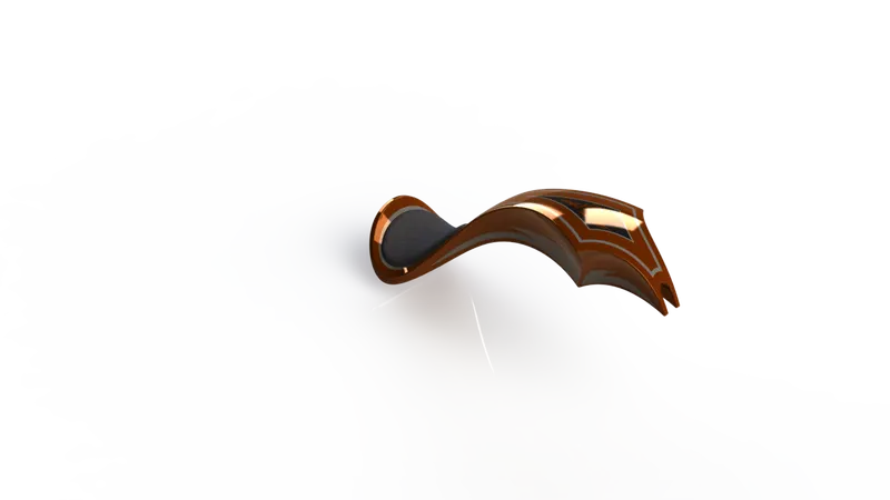
Fig14: Gas Tank
Final images of the model:
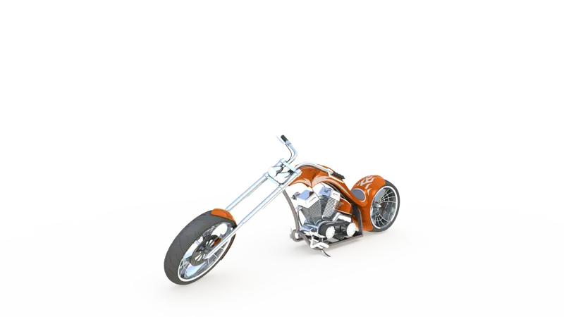
Fig15: Camera Setup View
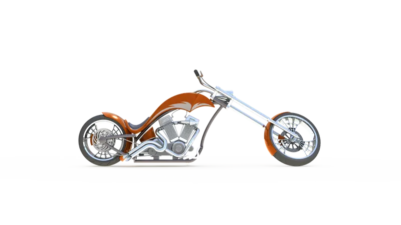
Fig16: Front View
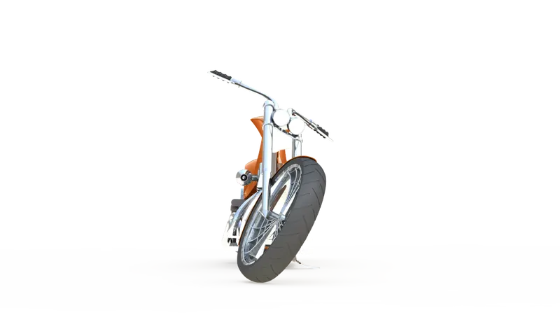
Fig17: Side View
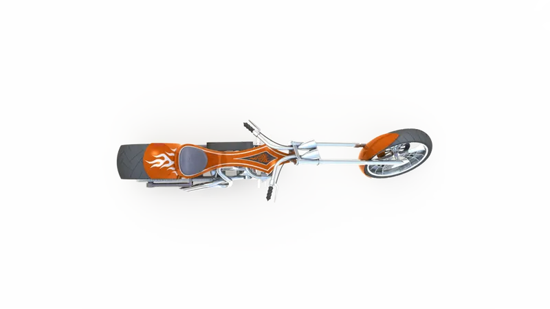
Fig18: Top View
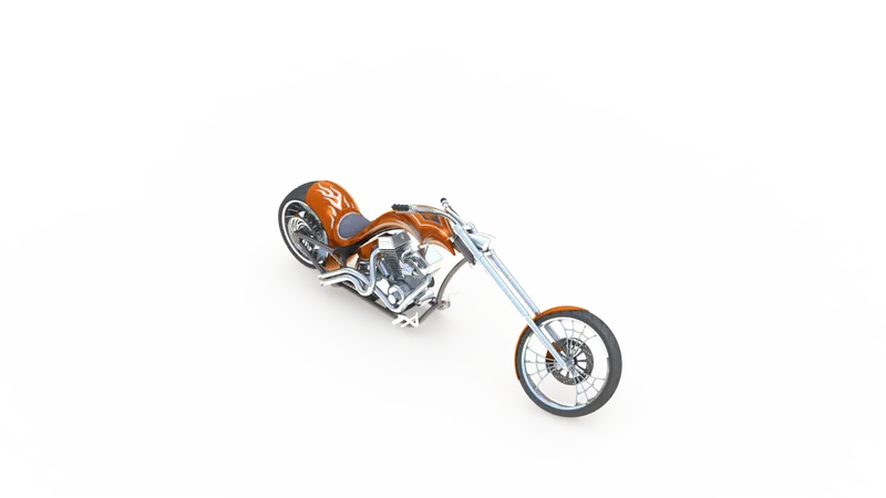
Fig19: Isometric View
Conclusion:
While designing this model in SolidWorks we get to learn about the various important tools and features of the software right from the basic level to the more advanced levels. We get to learn about how to use simple features such as Boss-Extrude, Boss-Revolve, etc. as well as the more complex tools such as Projected Curves, Projected Surfaces, etc.
We also get a good glimpse of the Photo View 360 feature while creating our final rendered images.