Wiring harness design in CATIA V5 - 3D modeling Week 7 Challenge
AIM-:
- Define the mechanical part electrically.
- Prepare Bundle Flattening in CATIA Flattening Workbench.
- Create 2d drawing of the bundle with different color coding with protection covering..
1. CHALLENGE 3 DRAWING
- Open Assembly drawing of “Challenge 3 drawing”.
- Go to the “File” then select “Save Management” option.
- “Save as” the Product file in “New Folder”.
- Then go to the “Propagate Directory” and click on ok.
- Change the Color of the Branch and connector.
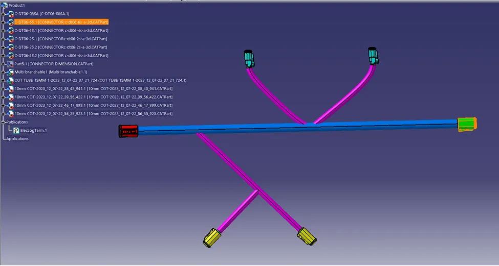
2. FLATTENING OF DRAWING
- Flattening of Drawing is very much important to show all part in a Single Plane, with proper Branch and Bundle.
- All Connection, Bundle, Branch, Cot Tube etc. show in Front view in Flattening work bench.
- It is to represent the drawing to anyone in single plane.
A) FLATTENING SET UP
· Open Catia file.
· Go to the “Tools” command then choose “Option”.
· Select “Equipment & System” option, then select “Electrical Harness Discipline”.
· Select “Electrical Harness Flattening” then “General”
· Select “Add” option then give “Catalog Path” in it.
· Highlight “New From” option then click on ok.
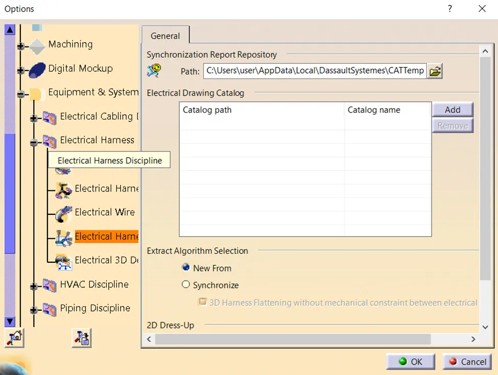
B) OPEN ELECTRICAL HARNESS FLATTENING
- Go to the “File” option.
- Select “New” then open “Product” workbench.
- Go to the “Start” then “Equipment & Systems” then “Electrical Harness Discipline” then choose “Electrical Harness Flattening”.
- Thus Electrical Harness Flattening workbench is open.
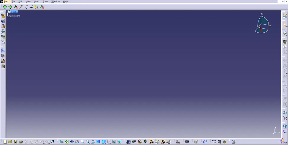
C) SET HARNESS FLATTENING PARAMETERES
- Select “Harness Flattening Parameters” option.
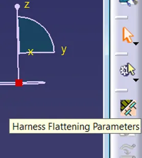
i) GENERAL
- Go to the “General” option.
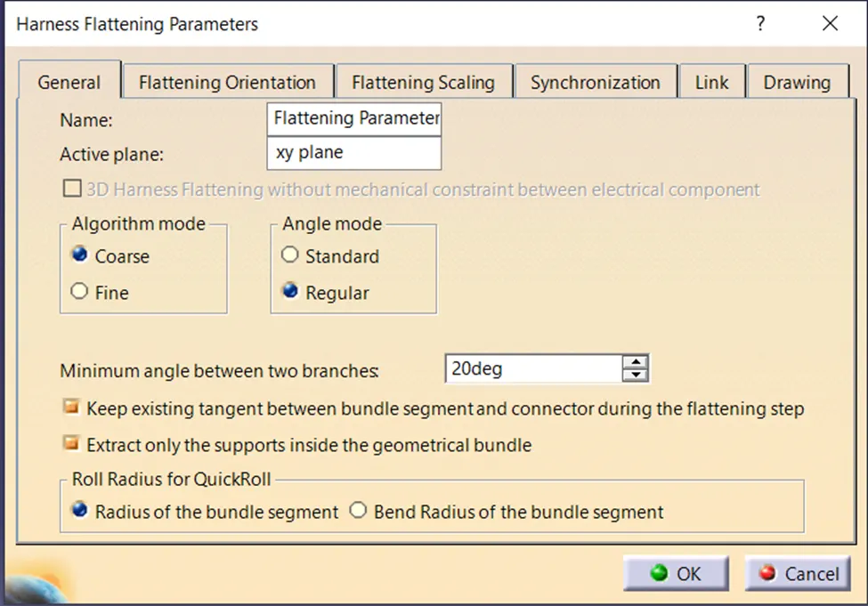
- Give the “Name” of Flattening Parameter and Select “xy plane” in “Active Plane”
- Highlight “Coarse” option in “Algorithm mode”.
- Highlight “Regular” option in “Angle Mode”.
- Give “20 deg” value in Minimum angle between tow Branch.
- Highlight “Radius of the bundle segment option as shown in below image.
ii) FLATTENING ORIENTATION
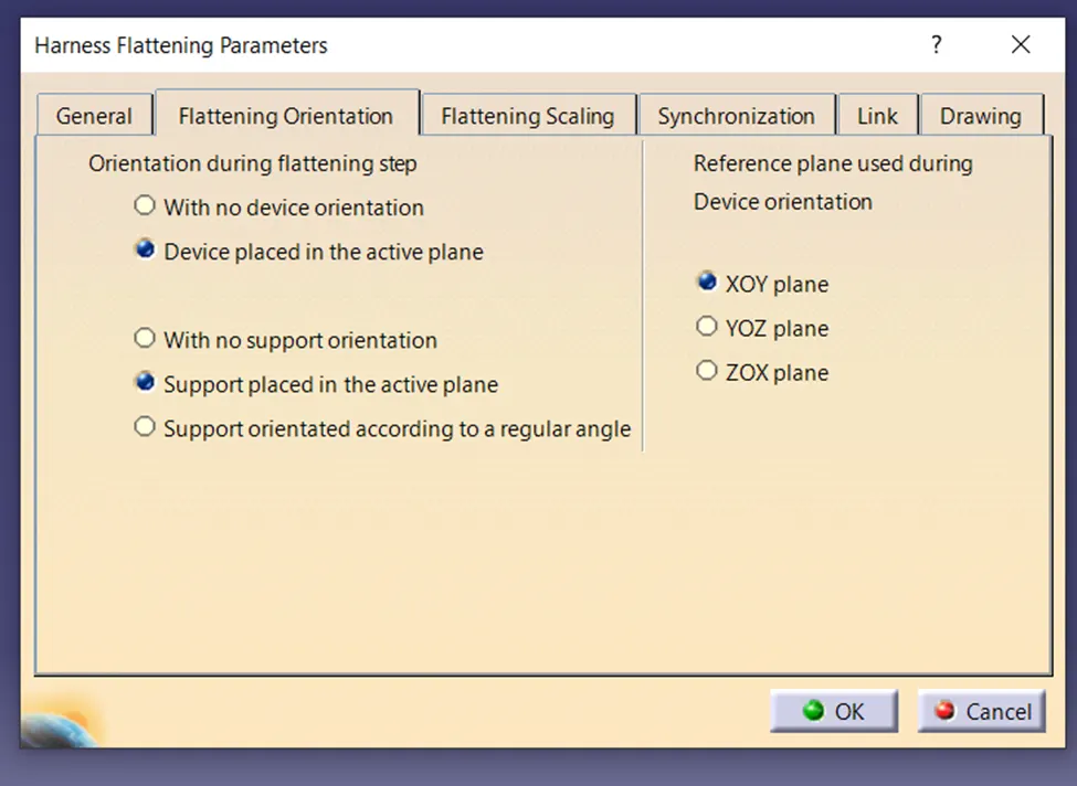
- Go to the “Flattening Orientation” option.
- Highlight “Device placed in the active plane”.
- Highlight “Support placed in the active plane”.
- Select “XOY’ plane.
iii) FLATTENING SCALING
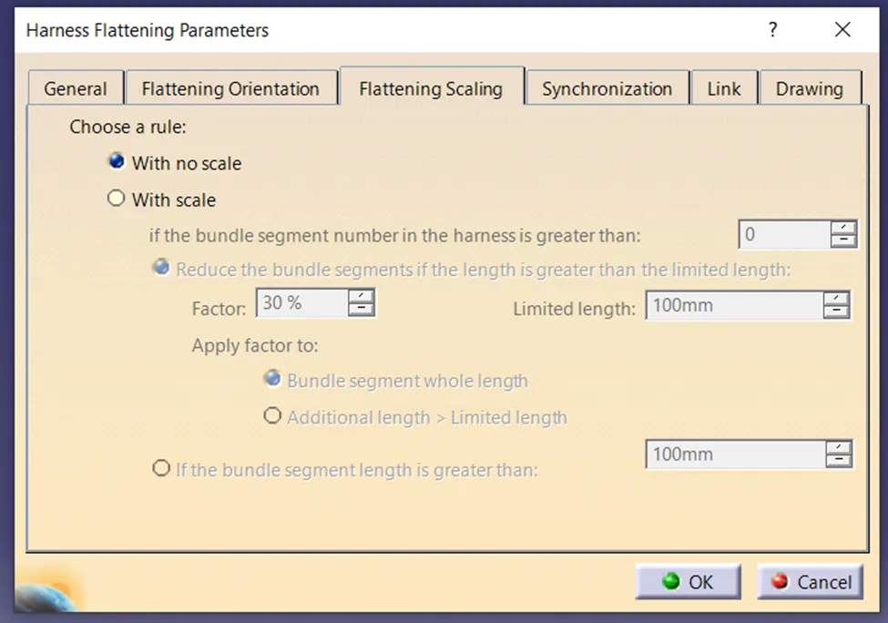
- Go to the “Flattening Scaling” option.
- Select “With no Scale” from “Choose a rule” option.
iv) SYNCHRONIZATION
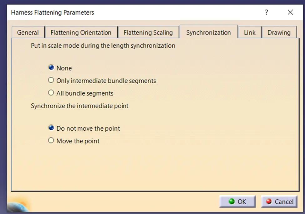
- Go to the “Synchronization option”
- Select “none” from “Put in scale during the length synchronization” option.
- Select “Do not move the point” from “Synchronize the intermediate point”.
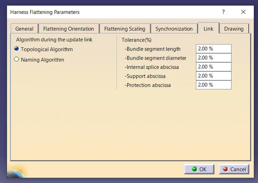
v) LINK
- Go to the “Link” option”.
- Highlight “Topological Algorithm” from “Algorithm during the update link” option.
- Give 2.00% for all as “Tolerance %”.
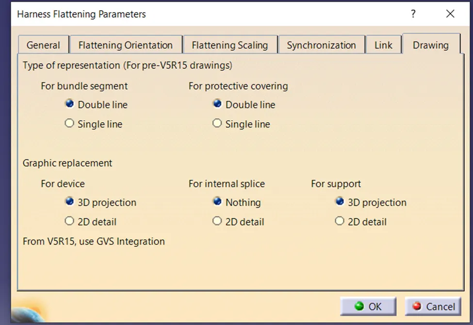
vi) DRAWING
- Select “Drawing” option.
- Highlight “Double line” for “bundle segment”
- Highlight “Double line” for “Protection Covering”.
- Highlight “3D projection for “Device”.
- Highlight “Nothing” option for “Internal splice”.
- Highlight “3D projection” option for “Support”.
- Then click on ok.
D) FLATTENING OF WIRE HARNESS
- Open the “Product file of “Wire Harness assembly”.
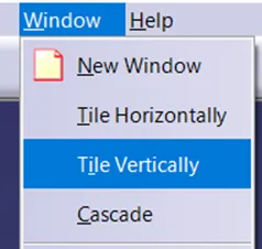
- Go the “Window” option
- Select “Tile Vertically” option and open both “Flattening workbench” and “Product assembly file” in one display.
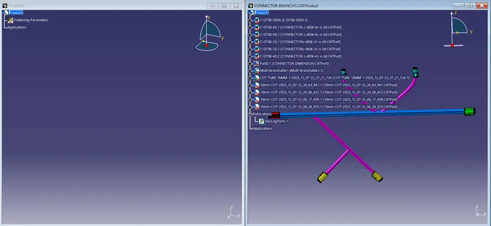
- When both files display on one screen, highlight the “Flattening Product” file.
- Click on the “Front” option, then select the Front face of the Connector from “Wire Harness Assembly” product drawing.
- Then update the file.
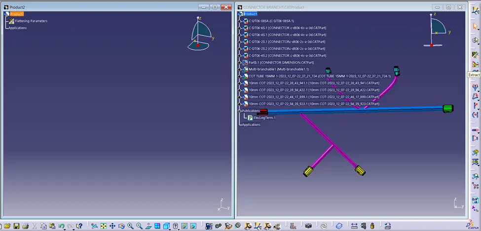
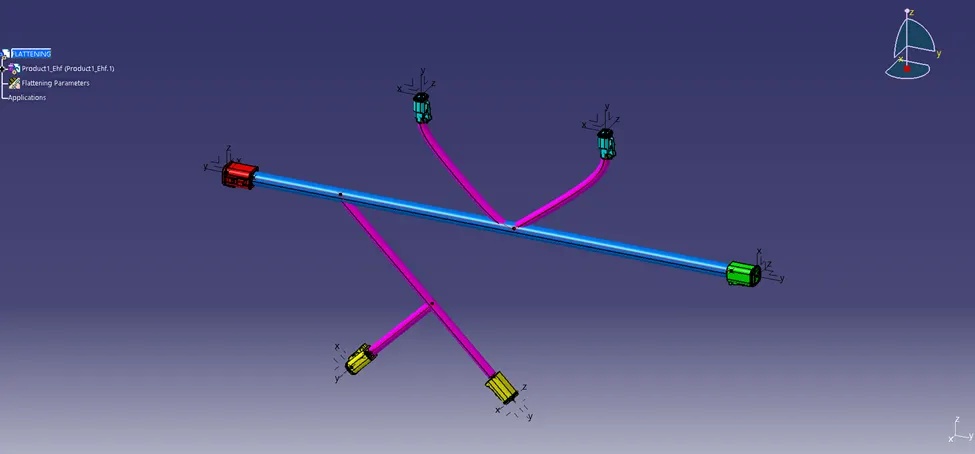
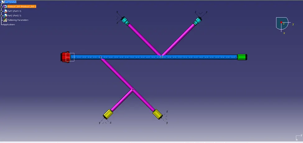
- “Wire Harness Assembly” drawing file shown as “Ehf.1” product file as shown below.
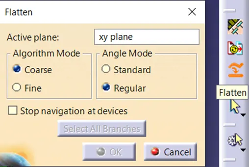
· Select “Flatten” command.
· Select “Coarse” as “Algorithm mode” and “Regular” as “Angle Mode”.
· On “Active Plane” choose “XY Plane” then click on ok.
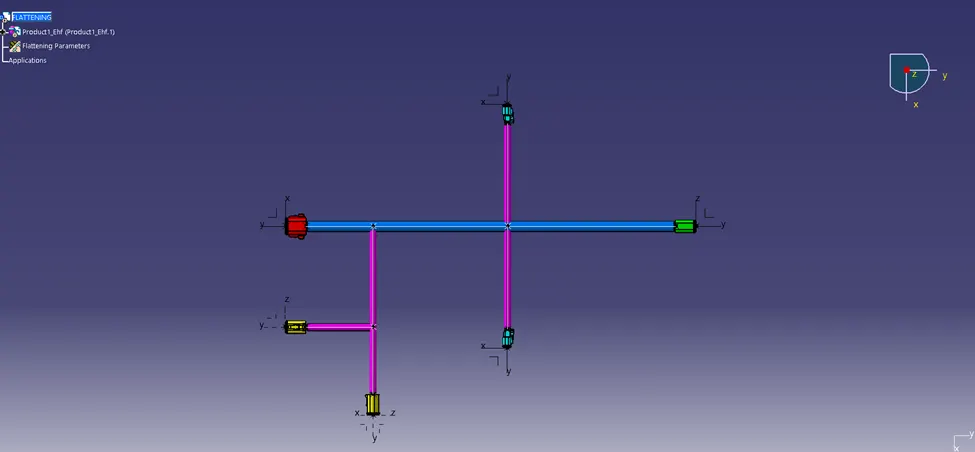
- Once click on ok, all the Branch of the drawing converted into Straight Horizontal and Vertical line.
E) MODIFICATION OF FLATTENING OF WIRE HARNESS
i) ROTATE
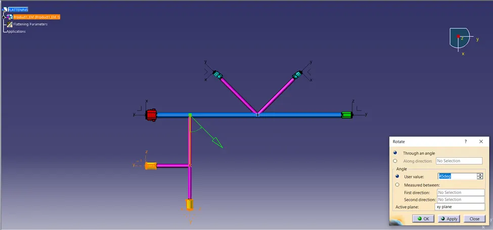
- To show the Branch in particular angle, select “Rotate” option.
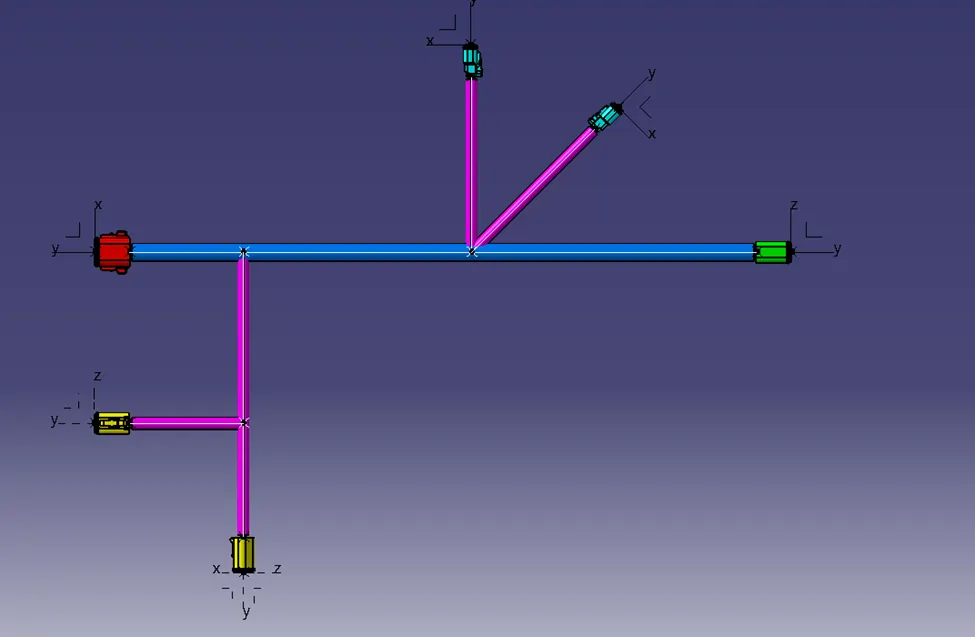
- Select the Branch, which whom want to Rotate.
- Put the value of angle in “Use Value” option.
- Select Active plane then click on ok, Branch is appeared at desire position.
- If branch is not “Rotate” properly, then click on “Update” option. All Branch were updated then.
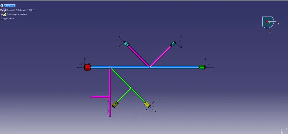
ii) COMPASS ROTATION
- By moving Compass on the Component and then highlight the component by clicking the file from “Feature Tree”.
- When Compass is showing as green color, then by dragging compass axis, we can “Move” and “Rotate”.
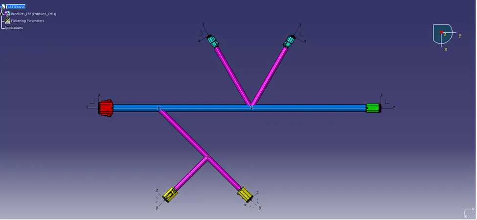
- Right click from the mouse on Compass, choose “Edit” option.
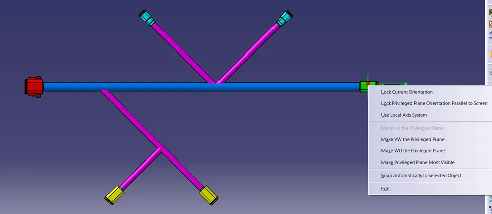
- Can Give the value of “Position” in any direction, either give value of “Angle” to Rotate it from axis.
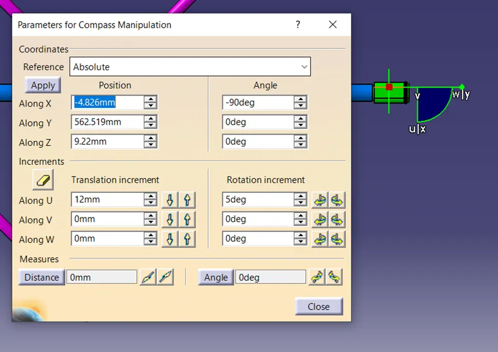
- Thus Orientation and position of Connector can be easily adjusted and direction of Connector is displayed from Front view.
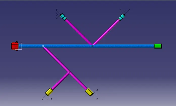
iii) QUICK ROLL
- By choosing “Quick Roll” option, we can Bend the Branch in some radius, where it is applicable to show.
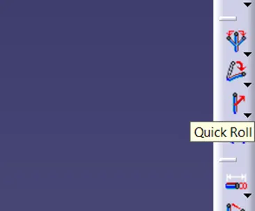
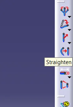
iv) STRAIGHTEN
- By Choosing “Straighten” option, we can give straightness of the Branch, if it is bend earlier.
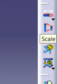
v) SCALE
- By selecting “Scale” option, the Branch length can be displayed by increasing or decreasing length in desired position.
- In this way, the actual length of the branch is not effected, only it is done to view the branch in desired position.
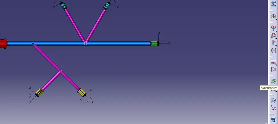
VI) SYNCHRONIZE
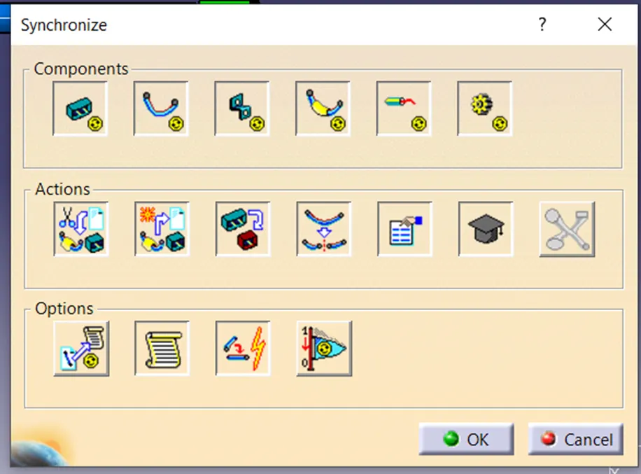
- Go to the “Synchronize” option.
- Highlight all “Components” by clicking all component shown under “Synchronize” option like “Devices”, Bundle Segments, Supports etc.
- Then click on ok.
- Update the file if required.
- Flattening of “Wire Harness Assembly” is done properly.
3. FLATTENING DRAWING LAYOUT
i) LAYOUT WORKBENCH
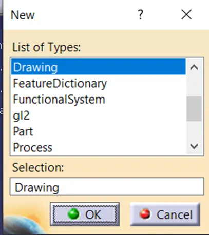
- Go to the “File” option, Select “New” then select “Drawing” option and click on ok.
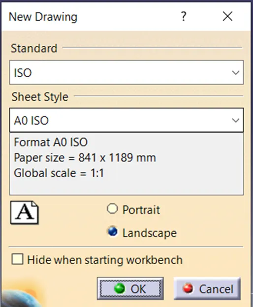
- In “New Drawing” parameter option, select “ISO” drawing as “Standard” drawing.
- Choose “A0 ISO” as “Sheet Style” option.
- Select “landscape” option, then click on ok.
ii) INSERT LAYOUT DRAWING
- Open the “Flattening drawing” as well as “Layout Workbench.
- Tile vertically both the drawing.
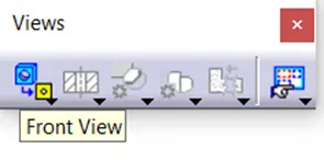
- Select “Front View” from “Views” option.
- Select the Front face of the “connector” to show it in front view.
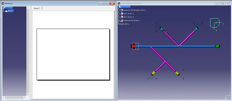
- After selecting Connector Face, the layout of flattening drawing, Click on layout page and flattening of the drawing is displayed as below.
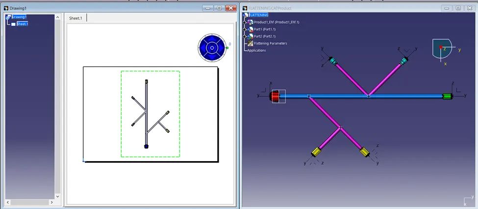
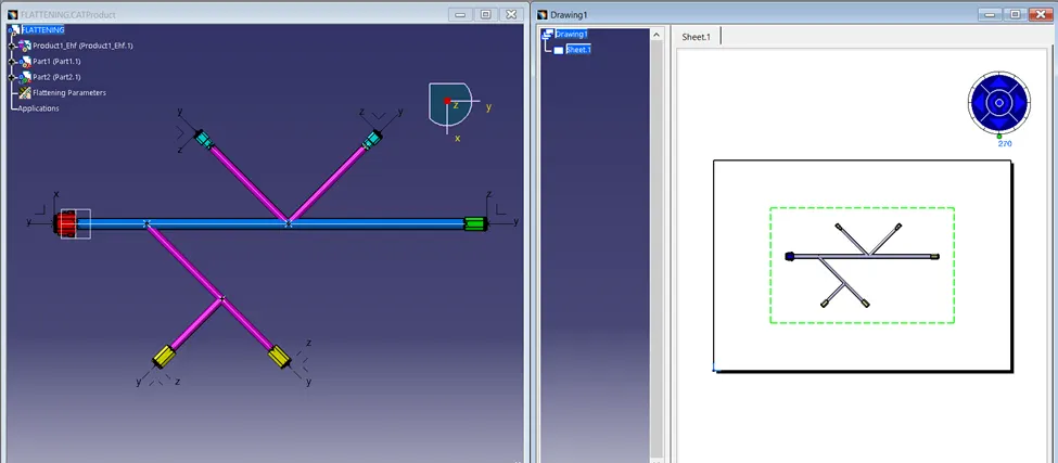
- Rotate the layout by selecting Compass and positioned the layout as horizontally.
- Update the file, then close the flattening drawing.
iii) PROPERTIES
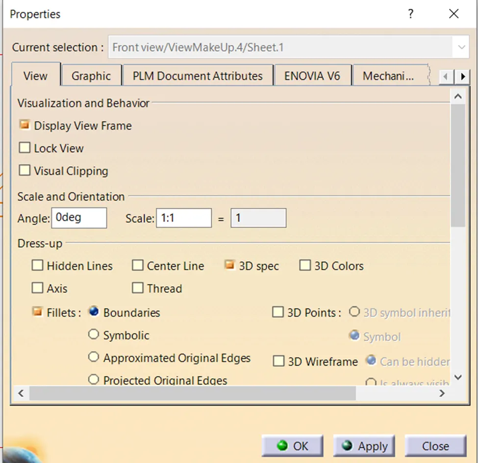
- Right click on the boundary of the layout drawing, select properties option.
- Can change the size of the sheet.
- Also increase or decrease the view mode by giving “Scale” value.
- Select “Landscape” option and Select Projection method.
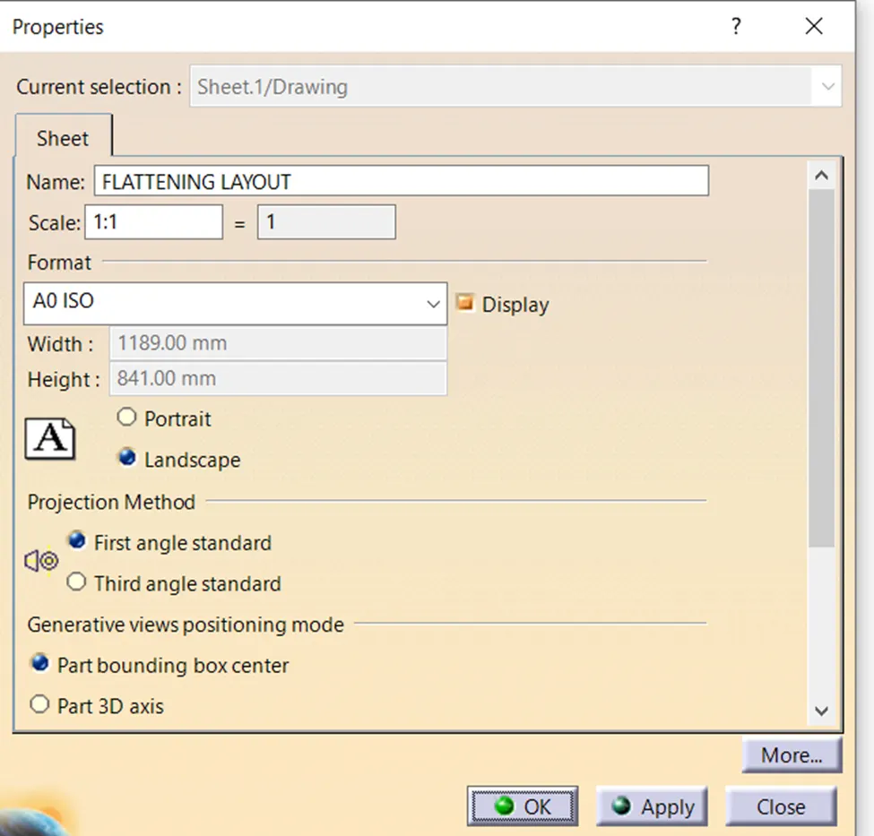
- Can show Hidden lines, Center line, 3d spec, 3d colors, axis and thread as per required through “Dress up” option.
- Highlight “Fillet” and “Boundaries” option, then click on ok.
iv) DRAWING LAYOUT
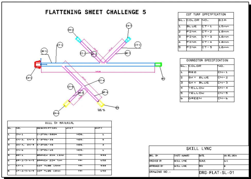
- Show the dimension of branch.
- Show the part number on drawing layout.
- Prepare a proper “Bill of matetial” by giving all details on it.
- Show the Protection Covering identity.
- Give all details, so that one can understand the drawing easliy.
- Give a proper naming of the drawing details, date and drawing sheet number.
- Show all component by numbeing and by different color for different component.
CONCLUSION
Flattening of drawing is very useful to represent drawing to anyone. All the details is given in the drawing, which anyone can easily understand. All the drawing is create on front view.