Wiring harness design in CATIA V5 - 3D modeling Week 7 Challenge
WIRING HARNESS FLATTENING
Objective
This project aims to flatten the input file of the wiring harness geometrical bundle set, adhering to design guidelines, and integrate the flattened view into a drawing sheet with distinct dress-up features for bundles and protective coverings.
Overview
Flattening of Wiring Harness
The Electrical Harness Flattening operation involves transforming the 3D format of wiring harness geometrical bundles into associated 2D drawings. This process proves invaluable during various stages of manufacturing, assembly, and installation.
In manufacturing, precision in design is paramount to prevent costly errors and delays. Collaboration between harness designers and manufacturing is crucial. CATIA – Electrical Wire Harness Flattening facilitates automatic and comprehensive flattening of 3D Electrical Harnesses for manufacturing documentation within a concurrent engineering environment.
Procedure
Product File Setup and Component Addition
- Create a new product file for wiring harness flattening and switch to the electrical harness flattening workbench.
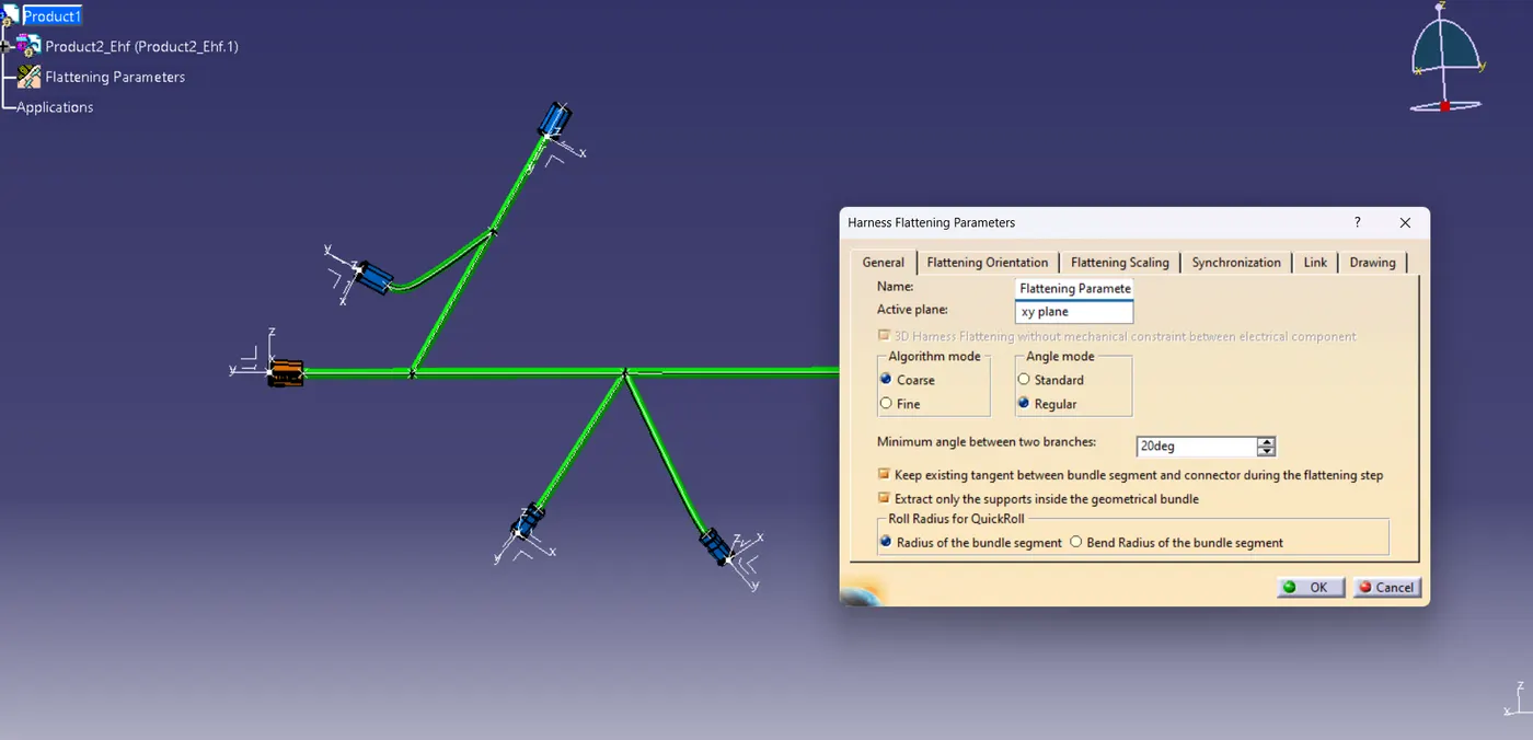
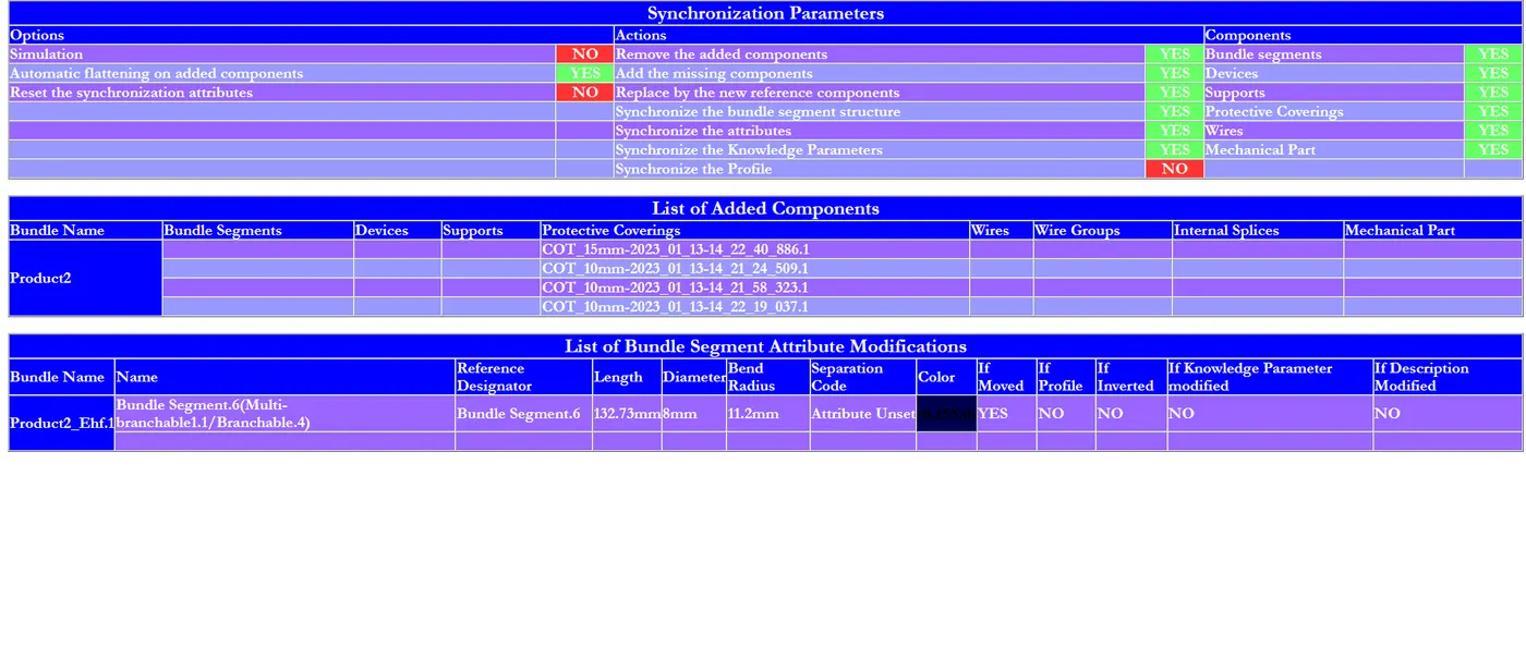
- Utilize the harness flattening parameters command to set initial parameters such as algorithm, angle mode, minimum angle between branches, flattening orientation, scaling, synchronization, link, and drawing options.
- Open the input file of the wiring harness geometrical bundle product in a new window, ensuring bundle continuity and electrical definition in the assembly.
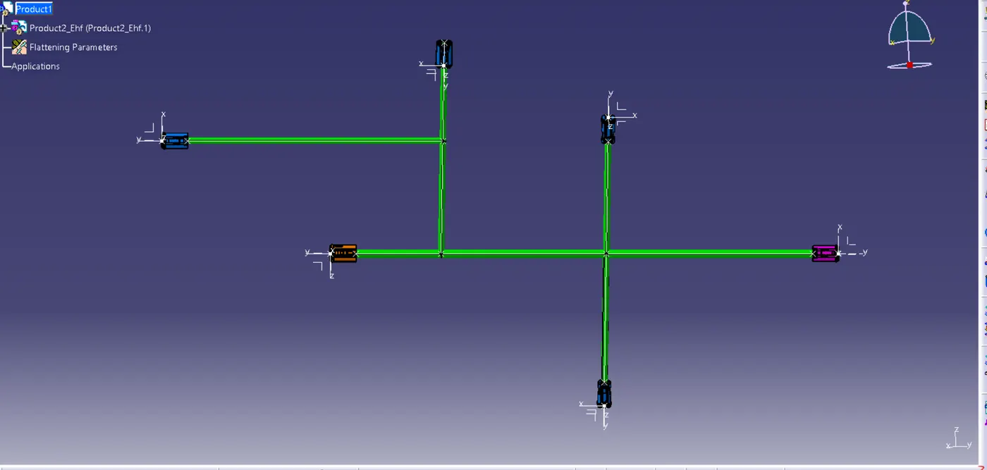
- In the wiring harness flattening product file, import the geometrical bundle product using the extract command, with the imported file having the .ehf suffix.
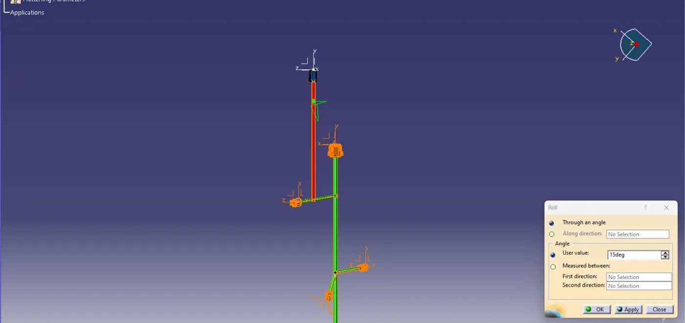
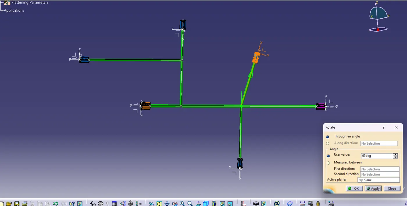
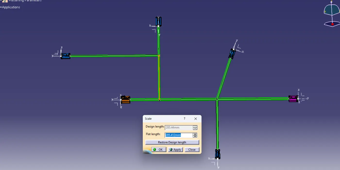
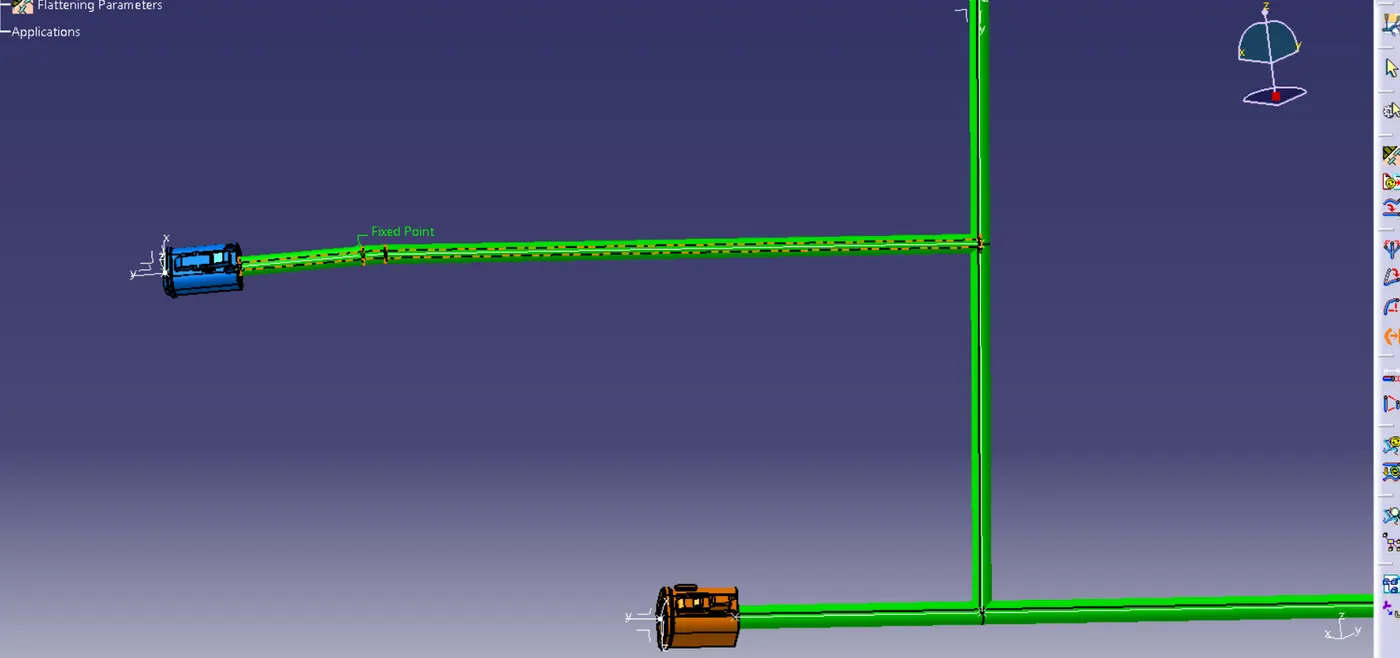
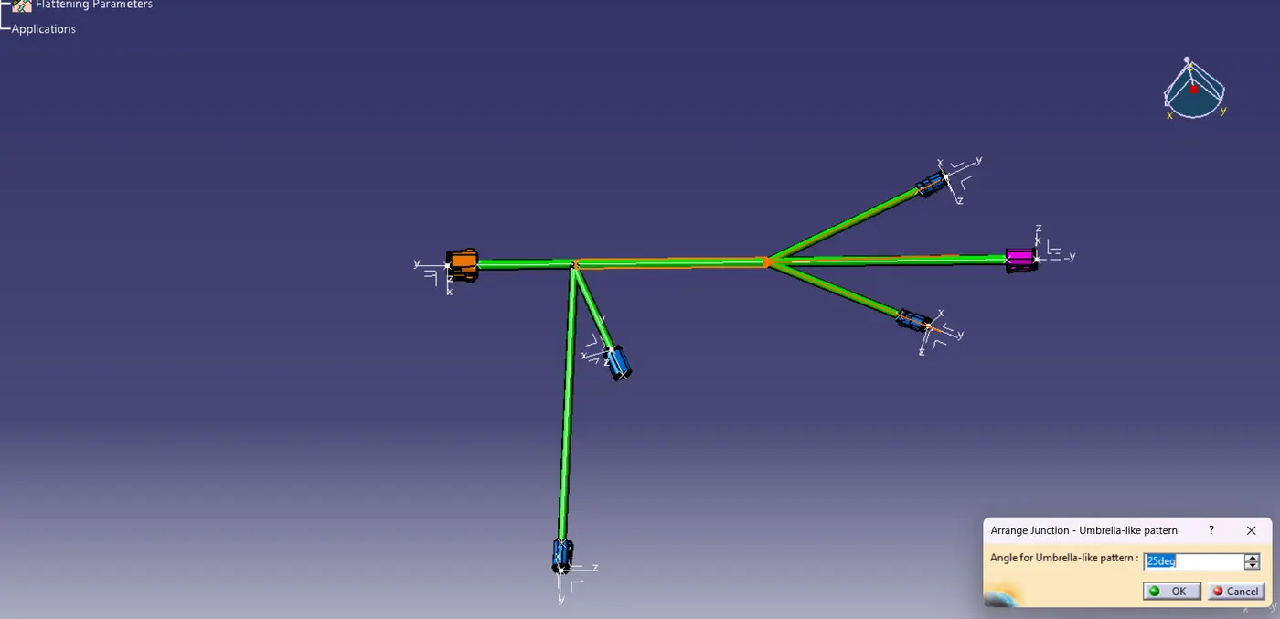
- Select the appropriate plane and all bundles, then flatten them using the flatten command. Adjust positions and angles as needed using commands in the electrical harness flattening workbench. Save all files in a dedicated folder for streamlined operations.
Drawing Creation and 2D Conversion
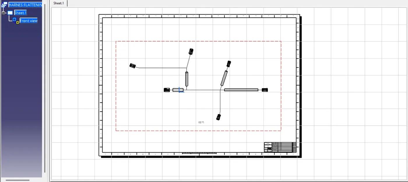
- Open a new drawing file, specifying settings like standard, paper size, and view type.
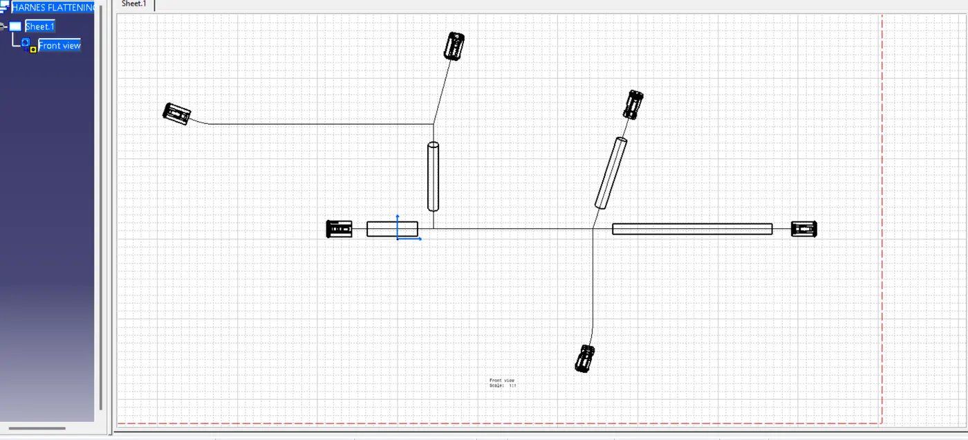
- Add the front view of the flattened wiring harness assembly to the drawing workbench using the front view command, selecting the appropriate flatten surface from the electrical harness flattening workbench.
- Right-click on the design sheet border, access properties and view options, and enable 3D wireframe. Mark as always visible from the dress-up feature.
- To enable 3D views of the connector, switch to the electrical flattening workbench, double-click the flattening parameters in the tree structure, adjust the graphic replacement of the device to 3D projection, and add a new front view to the drawing.
- Incorporate a frame and title block into the drawing using the toolbar insert, drawing, frame, and title block.