Wiring harness design in CATIA V5 - 3D modeling Week 7 Challenge
AIM: To flatten the harness assembly completed in “ week 4 challenge”. Place the flattened view on drawing sheet. Ensure bundles with protective coverings have different visuals on drawing view.
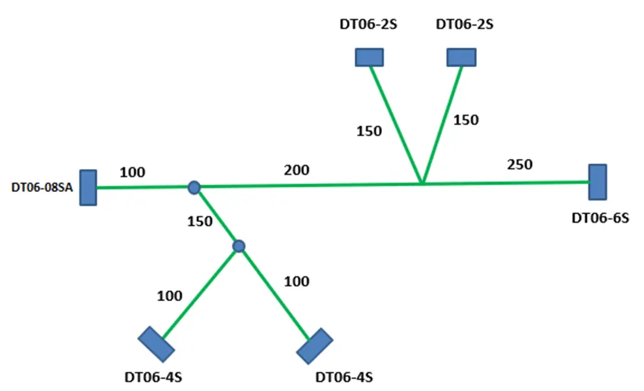
<!--[endif]-->
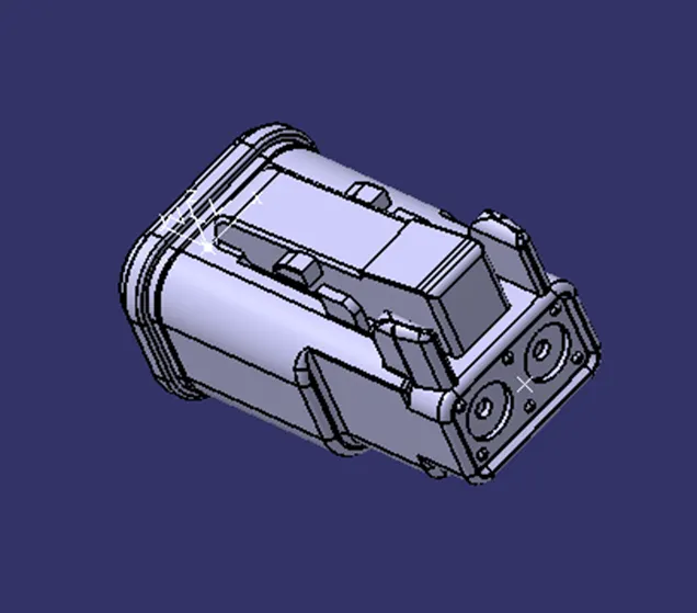
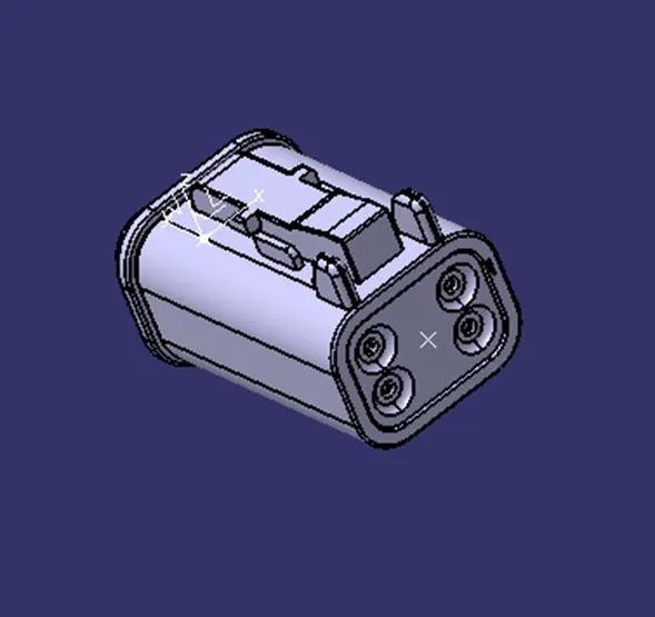
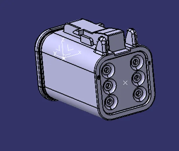
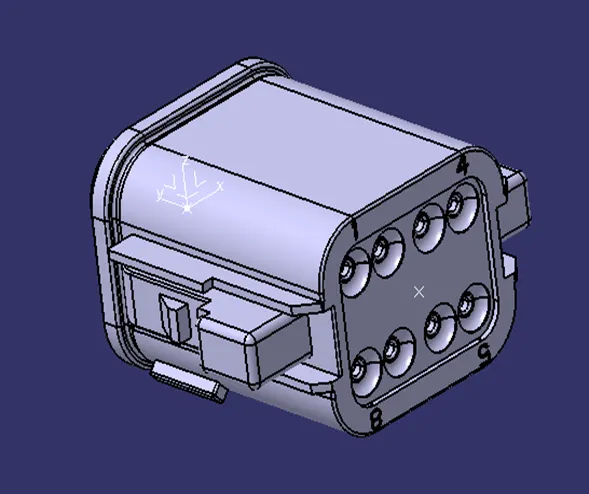
Step 1: Define parts as ‘Electrical’
<!-- [if !supportLists]-->a) <!--[endif]-->DT06-2S
<!--[endif]-->
<!-- [if !supportLists]-->b) <!--[endif]-->DT06-4S
<!--[endif]-->
<!-- [if !supportLists]-->c) <!--[endif]-->DT06-6S
<!--[endif]-->
<!-- [if !supportLists]-->d) <!--[endif]-->DT06-08SA
<!--[endif]-->
Step 2: Wiring Harness Routing Assembly
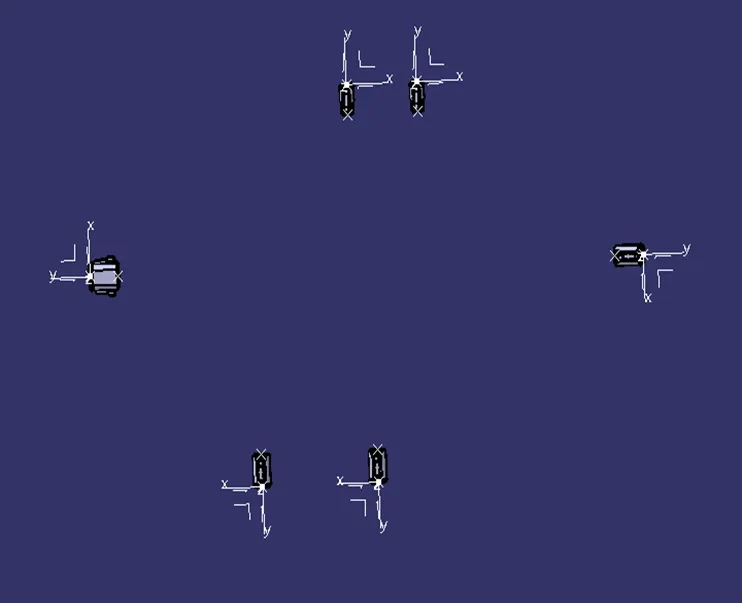
<!-- [if !supportLists]-->a) <!--[endif]-->Placement of Assembly Components:
Before creating the electrical routing between the components of the assembly, firstly the components have to be placed in their respective positions using various manipulation commands in the ‘Assembly Design’ workbench under the ‘Mechanical Design’.
<!--[endif]-->
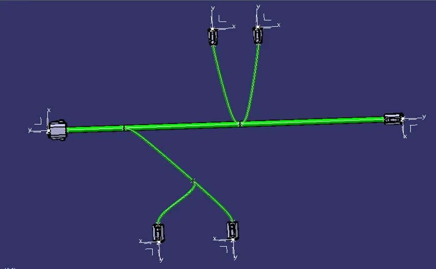
<!-- [if !supportLists]-->b) <!--[endif]-->Multi-Branchable Document
Then traverse into the ‘Electrical Harness Assembly’ workbench and select the product to electrify the geometric bundle. Then using the ‘Multi-Branchable Document’ command creates the bundle between the components of the product assembly.
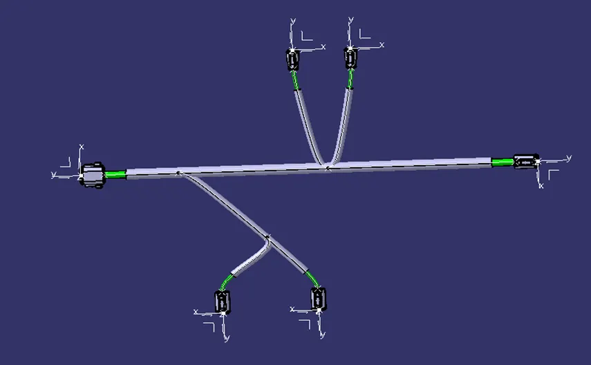
<!-- [if !supportLists]-->c) <!--[endif]-->Protection Covering
Add the relevant protection covering to the bundle segments.
<!--[endif]-->
Step 3: Prepare Bundle Flattening
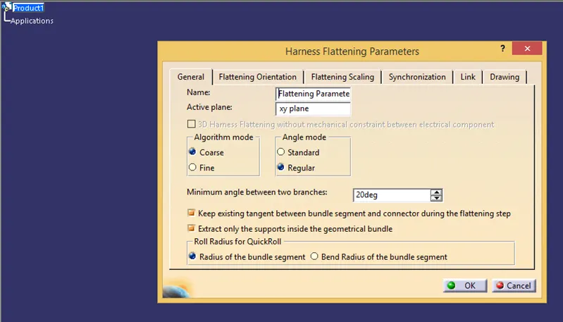
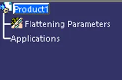
To prepare bundle flattening for the wiring harness routing assembly, first crate a new product file and save it in the same directory as that of the 3D Harness assembly and traverse into the ‘Electrical Harness Flattening’ workbench and then set the harness flattening parameters for the current project.
<!-- [if !supportLists]-->a) <!--[endif]-->Harness Flattening Parameters
<!--[endif]-->
 <!--[endif]-->
<!-- [if !supportLists]-->b) <!--[endif]-->Extract 3D Harness
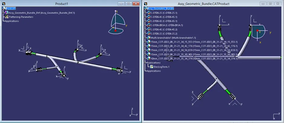
Open the 3D harness n another window and tile both the windows vertically. Then Extract the 3D Harness into the flattening product window using the ‘Extract’ command.
<!--[endif]-->
<!-- [if !supportLists]-->c) <!--[endif]-->Flatten
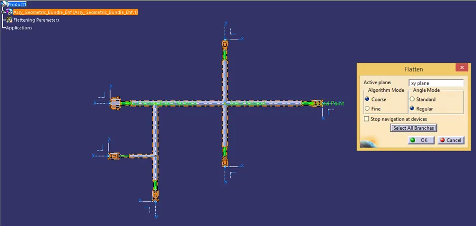
Then use the ‘Flatten’ command and then select all the branches of the 3D Harness to flatten the assembly with respect to the intended plane.
<!--[endif]-->
<!-- [if !supportLists]-->d) <!--[endif]-->Rearrange the bundles
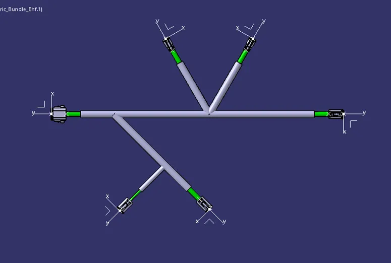
Use the ‘Manipulator’ command to rearrange the bundles to their intended positions and then save the file.
<!--[endif]-->
<!-- [if !supportLists]-->e) <!--[endif]-->2D Drawing of Bundle
To create a 2D Drawing of the bundle, first synchronize the flattened view and update the flattened link with respect to the 3D Harness file if there is breakage of the link between the two. Then open a new drawing file and select a plane to represent it onto the drawing sheet. Then click somewhere on the drawing sheet.
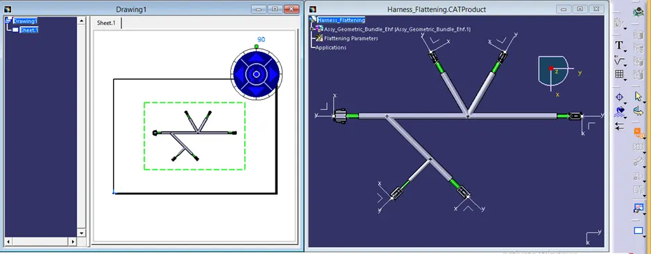
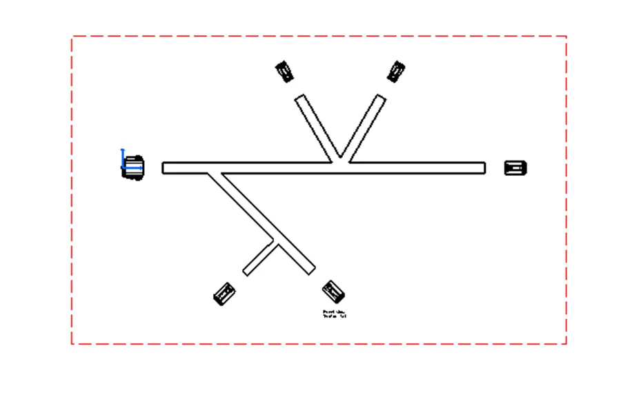
Then click somewhere on the drawing sheet. It can be seen that some elements of the drawings are missing.
<!--[endif]-->
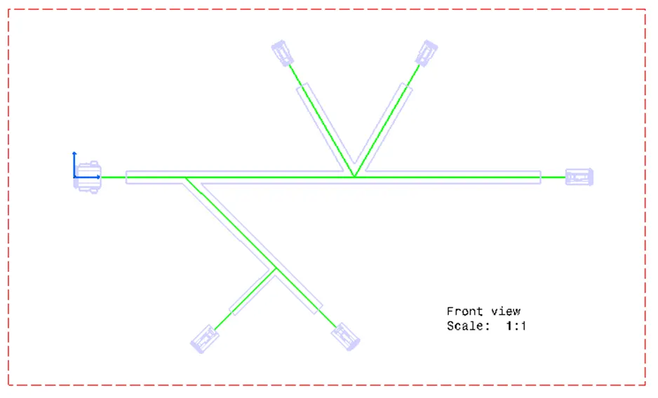
Change the properties of the drawing such that the 3D Wireframe command is always made visible and also make sure the 3D colours are enabled.
<!--[endif]-->